Microlen array based laser beam divegence angle testing method

A technology of microlens array and testing method, which is applied in the field of optics and can solve the problems of poor real-time testing and large measurement errors

Inactive Publication Date: 2007-08-08
HARBIN INST OF TECH
View PDF0 Cites 27 Cited by
  • Summary
  • Abstract
  • Description
  • Claims
  • Application Information

AI Technical Summary

Problems solved by technology

[0003] The purpose of the present invention is to provide a laser beam divergence angle testing method based on a microlens array to overcome the defects of large measurement errors and poor real-time test performance of existing beam divergence angle testing methods

Method used


Image

  • Microlen array based laser beam divegence angle testing method

Examples


specific Embodiment approach 1

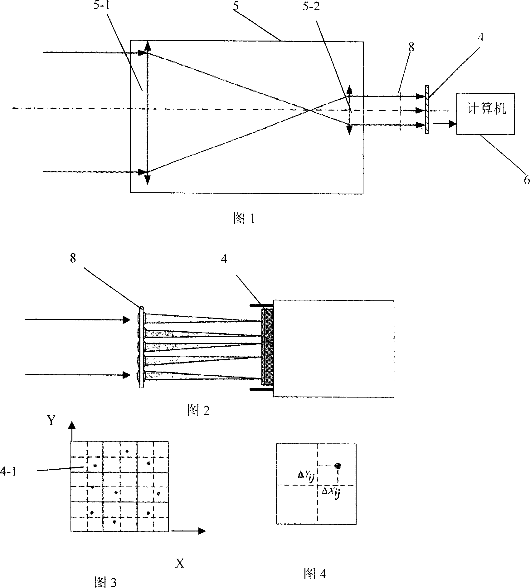
[0015] Specific Embodiment 1: The present embodiment will be specifically described below with reference to FIG. 1 to FIG. 4 . This embodiment is realized through the following steps: 1. The measured light beam is incident on the telescope system 5 made up of lens 5-1 and lens 5-2, so that the spot diameter of the output measured light beam matches the external dimensions of the microlens array 8 , the microlens array 8 includes m×n identical sub-lenses 8-3 arranged in a matrix; two, the microlens array 8 divides the light spot of the measured light beam into m×n groups of sub-beams, and focuses the sub-beams On the focal plane, m×n sub-spots are formed; 3. Use the area array CCD detector 4 to detect the sub-spots, the photosensitive surface of the area array CCD detector 4 is divided into m×n sub-detection areas 4-1, each sub-spot The optical axis of the lens 8-3 passes through the center point of a sub-detection area 4-1; when the sub-beam transmission direction is parallel ...

specific Embodiment approach 2

[0024] Specific Embodiment 2: The present embodiment will be specifically described below with reference to FIG. 1 . The difference between this embodiment and Embodiment 1 is that the telescope system 5 adopts a transmission telescope with an aperture of 300 mm and a magnification of 50. It can compress the spot diameter of the measured beam by 50 times. Other steps are the same as the first embodiment.

specific Embodiment approach 3

[0025] Specific embodiment three: the difference between this embodiment and embodiment one is: the sub-lenses 8-3 in the microlens array are arranged in a square matrix of 64×64, and the focal length of each sub-lens 8-3 is 1 mm, and the diameter is 0.1 mm . Other steps are the same as the first embodiment.


PUM


Abstract

The invention is a laser beam divergence angle testing method based on the micro-lens array, and the invention belongs to the optical field, specifically relating to the laser beam divergence angle testing method. It overcomes the existing deficiencies of the existing beam scattered angle method with larger measurement error and less measurement real-time feature. It includes the following steps: the measured beam is incidence to the telescope system, matching the output beam diameter and the micro-lens array shape, and the micro-lens array contains mXn matrix sub-lens; using micro-lens array to divide the measured beam into the sub-beams, and through CCD to detect the launch angle of each sub-beam, and through statistical method to calculate the measured beam divergence angle, the measurement accuracy reaching 0.1mu rad. Because this method does not require the measurement light spot diameter, it avoids the problem that the light spot diameter is difficult to be accurately measured. This method in the invention is only measuring in the one position of the optical path; therefore the method can facilitate to realize the real-time measurement of the beam divergence angle.

Description

technical field [0001] The invention belongs to the field of optics, in particular to a method for testing the divergence angle of laser beams. Background technique [0002] Laser beam divergence angle is an important parameter of existing laser emitting devices, and its accurate measurement is an important issue in the development and application of high-precision laser emitting devices. Existing test methods generally measure the spot diameter at different positions, and calculate the beam divergence angle according to its variation with distance. In actual operation, due to the vignetting of the edge of the beam, it is difficult to measure the spot diameter accurately, resulting in a large measurement error. In addition, because this method requires multiple measurements at different locations, the real-time performance is poor. Contents of the invention [0003] The purpose of the present invention is to provide a method for testing laser beam divergence angle based ...

Claims


Application Information

Patent Timeline
Patent Type & Authority Applications(China)
IPC IPC(8): G01B11/26G01B21/22G01M11/00G01M11/02H01S3/00H01S5/00
Inventor 谭立英马晶韩琦琦刘剑峰于思源
Owner HARBIN INST OF TECH
Why Eureka
Try Eureka