A device for mechanical guiding, a lock module and a lock device comprising such a device

A technology of guiding device and lock module, applied in the field of lock module, lock device and component device, can solve the problems of unsuitable modular structure of lock device, energy consumption and space consumption of lock device, etc., and achieve compact structure and highly flexible structure. , to achieve the effect of modular structure

Inactive Publication Date: 2007-08-08
ASSA
View PDF2 Cites 10 Cited by
  • Summary
  • Abstract
  • Description
  • Claims
  • Application Information

AI Technical Summary

Problems solved by technology

However, the lock device shown consumes energy and space and is not suitable for modular construction of the lock device

Method used


Image

  • A device for mechanical guiding, a lock module and a lock device comprising such a device
  • A device for mechanical guiding, a lock module and a lock device comprising such a device
  • A device for mechanical guiding, a lock module and a lock device comprising such a device

Examples


Embodiment Construction

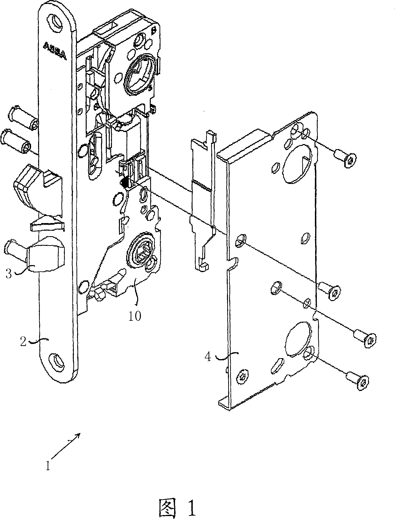
[0021] A preferred embodiment of a lock device comprising means for mechanically guiding the lock member will now be described first with reference to FIG. 1 .

[0022] FIG. 1 is a general view of a lock device generally indicated by reference numeral 1 . The lock arrangement comprises a front end 2 having a lock mechanism mounted thereon. The lock mechanism comprises conventional components such as a latchbolt 3, a hook bolt, a cylinder follower and the like. The locking mechanism is protected by a case (not shown) and a cover 4 .

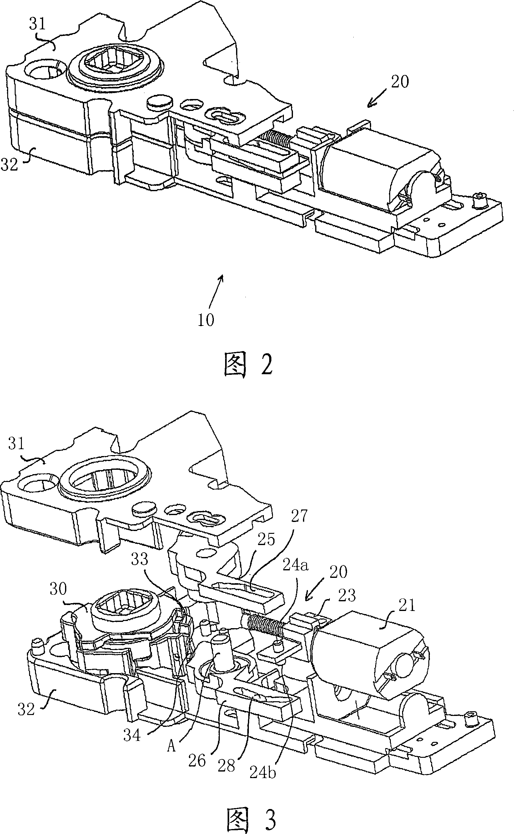
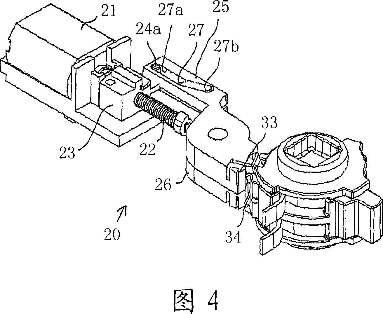
[0023] The lock mechanism also includes a lock module in the form of a lever handle follower unit 10 . This unit is intended to communicate with the arm guiding the movement of the latchbolt 3 between the extended and retracted positions. The lever handle follower unit (shown in more detail in FIGS. 2 and 3 ) includes a lever handle follower hub 30 through which a square peg is inserted into a square opening in the hub. A lever handle (not sho...


PUM


Abstract

A device for mechanically guiding components in a lock arrangement, preferably for guiding a follower unit, comprising an electrically actuable manoeuvring element (21) preferably a motor. A first engagement element (23,24) is coupled mechanically to the manoeuvring element for linear movement along a movement axis between a first and a second end position. A first arm (25) which is rotatable about a rotatable shaft (A) includes a second engagement element (27) located in mechanical engagement with the first engagement element. Because each of the first and second engagement elements (23,24,27) includes a groove (27) which extends at least partially out of parallel with the movement axis of the first engagement element, the first arm is caused to rotate when the first engagement element moves linearly. This results in a simple and flexible guide device.

Description

technical field [0001] The present invention relates generally to lock devices and, more particularly, to an arrangement for mechanically guiding components of a lock device. The invention also relates to a lock module and a lock device comprising such a component guide. Background technique [0002] Lock devices of this type are known in the prior art, with which it is desirable to mechanically actuate the lock member by means of an electrically actuatable operating element, such as an electric motor or a solenoid. A so-called electric lever handle lock is an example of such a device by which the lever handle function can be engaged or disengaged on one or both sides of a door equipped with such a device. [0003] It has been found that this known lock device has several disadvantages. One problem is that the electrically operable function of such locks requires the space required to provide the components. A further problem with such locking devices is that, for reasons...

Claims


Application Information

Patent Timeline
IPC IPC(8): E05B47/06E05BE05B47/00E05B63/16
CPCE05B47/0688E05B47/0012E05B63/16E05B2047/0016E05B2047/0023E05B2047/0025E05B47/0676
Inventor 谢尔·科林
Owner ASSA
Why Eureka
Try Eureka