
Electrical power switching with efficient switch protection

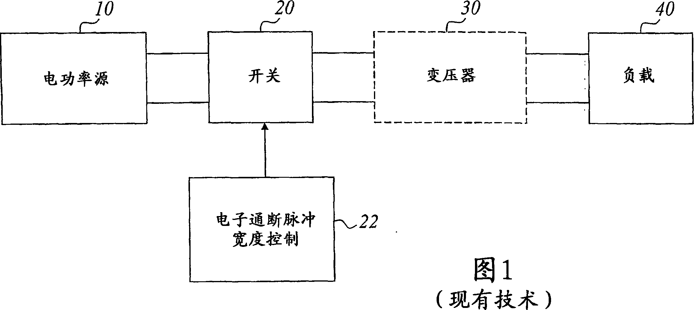
A technology of electric power and power, which is applied in the field of power switching and switch protection, and can solve problems such as shortening the life of IGBT

Active Publication Date: 2007-08-08
SCANDINOVA SYSTEMS AB
View PDF8 Cites 4 Cited by
  • Summary
  • Abstract
  • Description
  • Claims
  • Application Information

AI Technical Summary

Problems solved by technology

However, interrupting high current usually shortens the life of the IGBT in an unpredictable way

Method used


Image

  • Electrical power switching with efficient switch protection
  • Electrical power switching with efficient switch protection
  • Electrical power switching with efficient switch protection

Examples


specific example

[0098] Turning to a concrete example, assume that (for a 7.5 μs wide pulse) a delay line with a 4 μs delay time is built for a 12-block modulator. If the desired modulator load is 170kV, 120 amps, the load impedance is 1417 ohms. If a pulse transformer has a turns ratio of 170kV / 1200V = 142 (e.g. split core, half turns primary, 71 turns secondary), then the load reflected to the primary will appear to be 1417 / 142^ 2 = 0.07 ohms. Each of the 12 "independent" modules must drive a load of 0.07 x 12 = 0.84 ohms. The maximum pulse width (FWHM) is 7.5µs, so a delay line round-trip time of 8µs will sufficiently isolate the module from the load, making the tuning of the module independent of the operating point. It is important to note that regardless of the load impedance, it will not be necessary to change the pulse leveling or "tuning" components.

[0099] To get a more hands-on feel for the invention, some basic design calculations for an exemplary delay line with 0.84 ohm impe...


PUM


Abstract

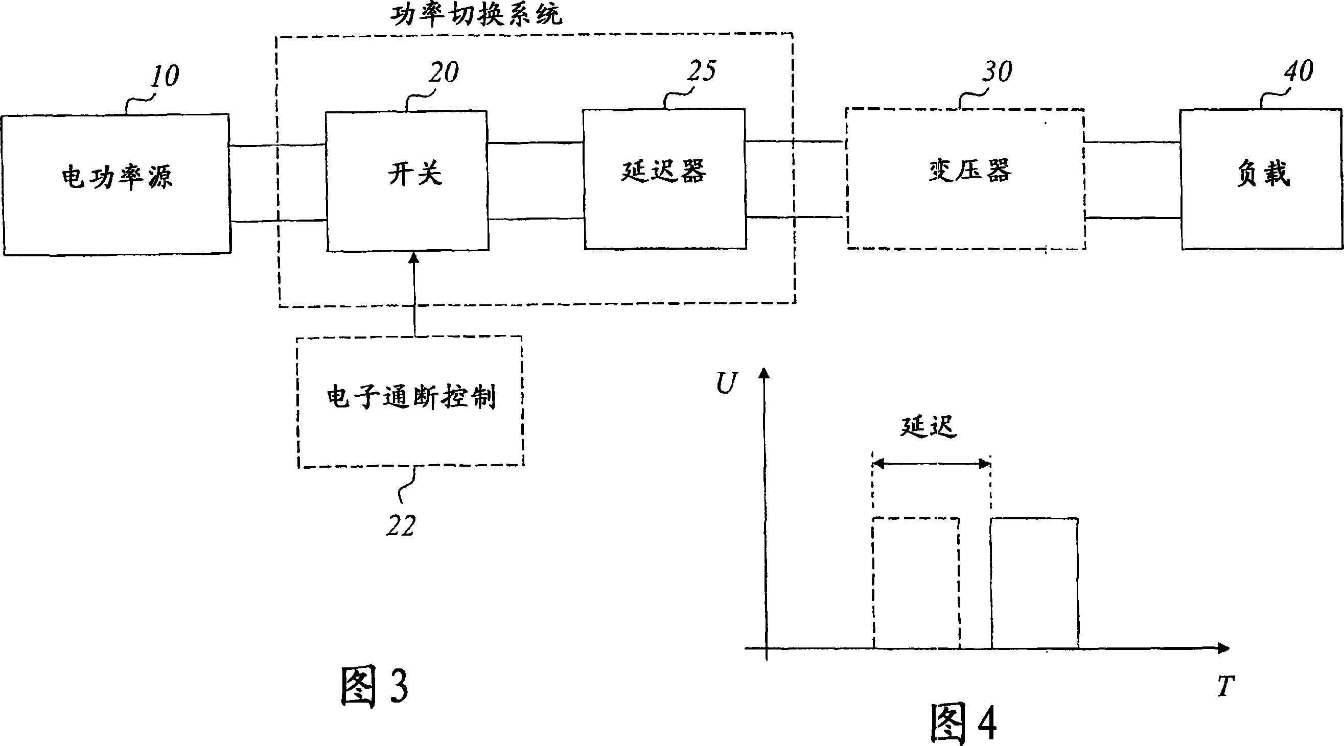
A basic idea of the invention is to introduce a transmission delay line (25) between the switch (20) and the power output side of a power switching system so that any sparking of the load (40) is hidden from the switch (20) by the time delay of the transmission line (25). This makes it possible to detect the load spark and actively protect the switch, typically by turning the switch off, before it actually knows that there has been a load fault spark. Alternatively, the delay of the transmission line is long enough so that the switch has already been turned off in normal pulse operation before the load fault current reaches the switch. Either way, the switch will be turned off under normal current flow and will not be subject to destructive over-current or over-voltage conditions.

Description

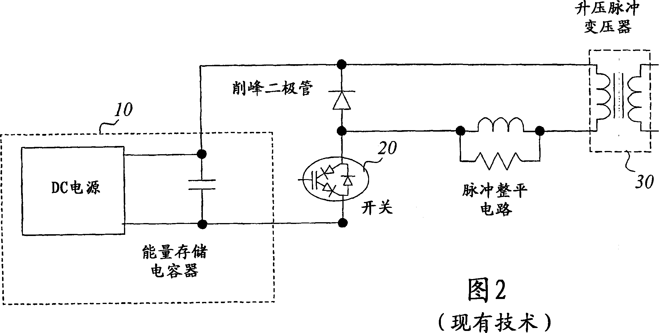
technical field [0001] In general, the present invention relates to electrical power systems, such as power generators, power modulators, etc., and more specifically to the problems of power switching and switch protection in such systems. Background technique [0002] Electrical power systems are found in almost all fields of industry and normally involve some form of power switching device for the controllably delivering electrical power, or energy, to an intended load. Electrical power switching is used in a wide range of applications such as locomotive traction, automobiles, conveyor belt systems, escalators, elevators, air conditioning equipment, electrical equipment, microwave systems, medical equipment, laser drives, and radar applications. [0003] A specific example of a commonly used power system is a power modulator, which can be viewed as a device that controls the flow of electrical power. When a power modulator is designed to generate electrical pulses, it is ...

Claims


Application Information

Patent Timeline
Patent Type & Authority Applications(China)
IPC IPC(8): H02H3/08H02H3/16H02H7/04H02H7/10H02H7/20H03KH03K3/57H03K17/082
CPCH03K17/082H03K3/57
Inventor 沃尔特·克鲁森马克·H·卡尔坦博恩
Owner SCANDINOVA SYSTEMS AB
Learn More