Contactor

A technology of contactors and static contacts, applied in the direction of relays, electromagnetic relays, detailed information of electromagnetic relays, etc., can solve problems such as unreliable wiring and large size

Active Publication Date: 2007-08-15
ZHEJIANG CHINT ELECTRIC CO LTD
View PDF0 Cites 19 Cited by
  • Summary
  • Abstract
  • Description
  • Claims
  • Application Information

AI Technical Summary

Problems solved by technology

[0003] The present invention aims to solve the problem of relatively large product volume in the prior art, and aims to provide a contactor with a compact structure
[0004] The present invention also solves the problem of unreliable wiring in the prior art, and aims to provide an improved contactor with convenient and reliable wiring

Method used


Image

  • Contactor
  • Contactor
  • Contactor

Examples


Embodiment Construction

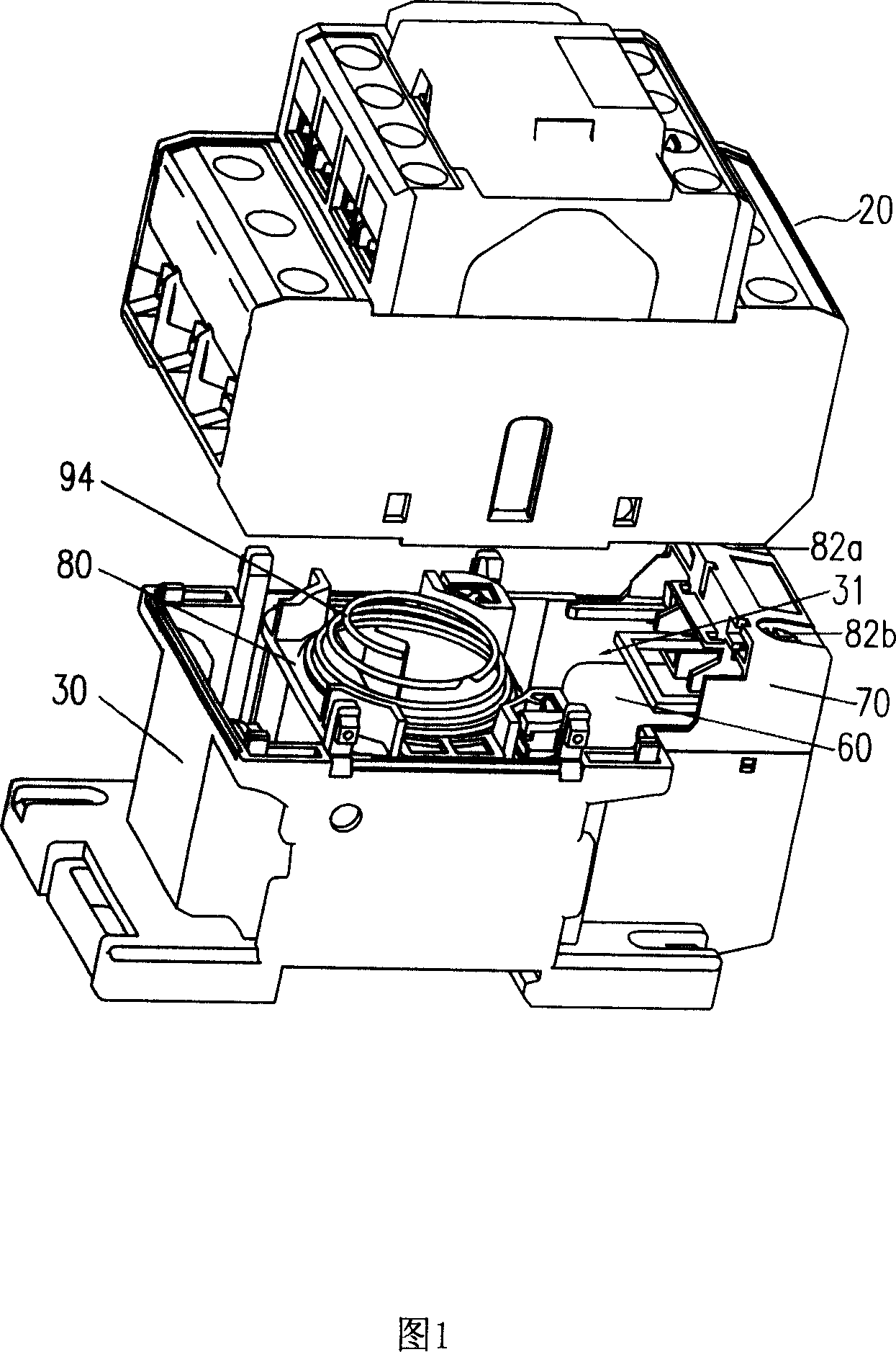
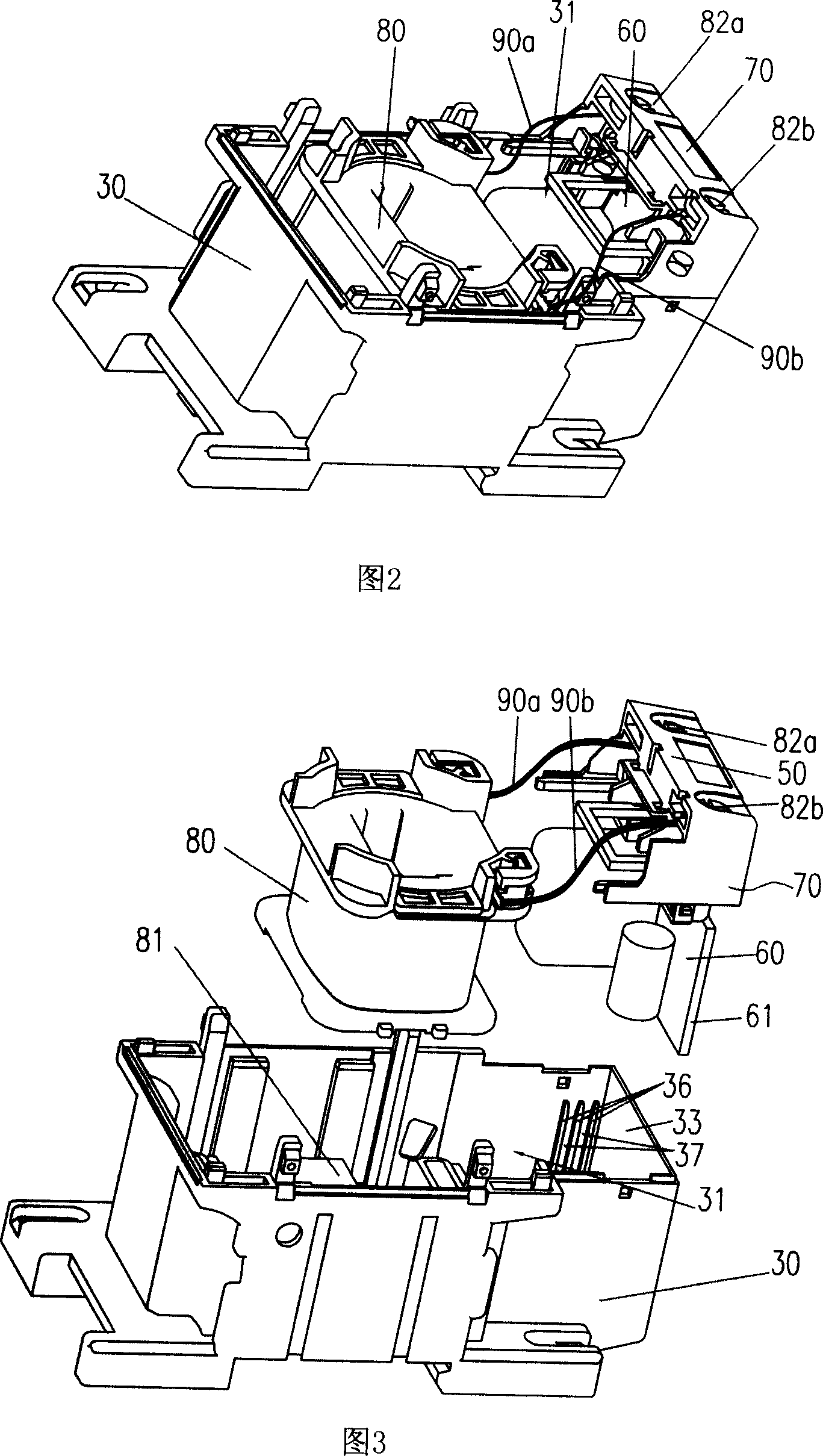
[0017] Referring to Figures 1 and 2, the contactor is provided with a base 30 and a base 20, and the base 20 is provided with a support (not shown in the figure), a return spring 94 and a static contact, and on the support A movable contact (not shown in the figure) is provided, and a coil 80, a fixed armature 81, and a pair of command terminals 82a, 82b are provided in the base 30, and a cavity 31 capable of accommodating the control circuit board 60 is also provided. When the voltage of the coil 80 rises to a certain value, a suction force is generated between the fixed armature 81 and the movable iron core to move the supporting member downward. Under the action of tension of the return spring 94, the iron core drives the supporting member to reset.

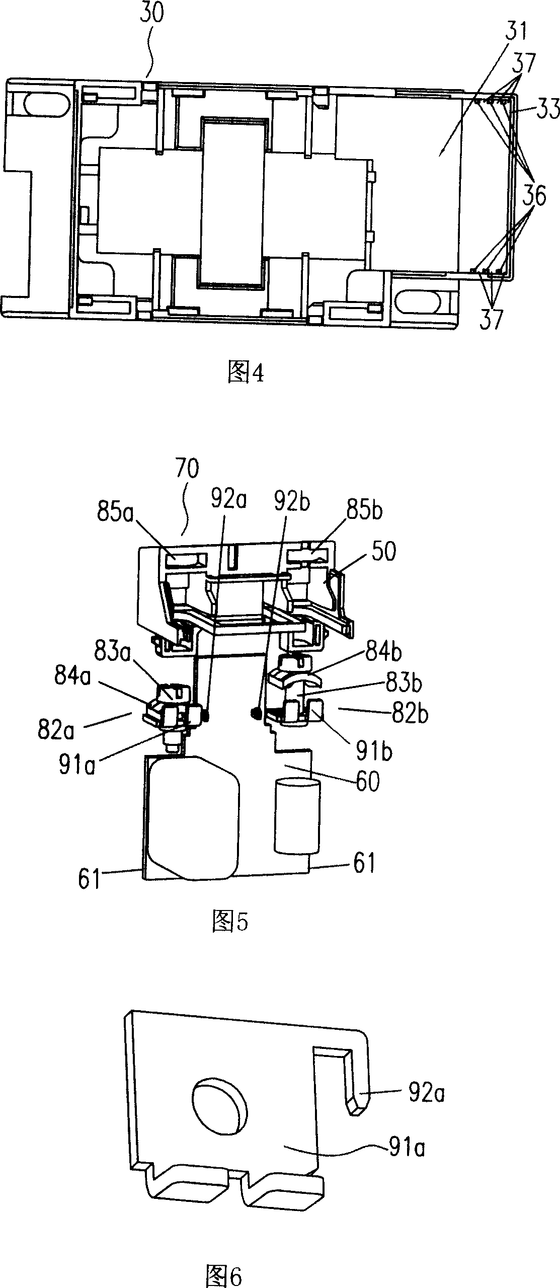
[0018] As shown in FIG. 3 , an exploded view of the base assembly, the edge 61 of the control circuit board 60 is inserted into the positioning groove 37 , thereby restricting the movement of the control circuit board in a dir...


PUM


Abstract

The disclosed contactor comprises: a bottom base, including a coil with a movable iron core, a fixed armature, a command terminal, and a control circuit board with input and output end connected with the command terminal and coil; and a base frame, including a support member with a moving contact to connect with former core, a reset spring, and a fixed contact.

Description

technical field [0001] The invention relates to a contactor. Background technique [0002] The existing contactor includes a base and a base, the base is provided with a support, a return spring and a static contact; the base is provided with a coil, a fixed armature and a command terminal; the support A movable contact is provided, and a movable iron core is arranged inside the coil, and the movable iron core is fixedly connected to the supporting member; both ends of the command terminal are respectively connected to the coil and an external control circuit. When the command terminal receives the energization signal of the external control circuit, the voltage signal is added to the coil. After the coil is energized, a suction force is generated between the fixed armature and the movable iron core to move the supporting member downward, so that the movable contact and the static contact Closed (for normally open contacts) or open (for normally closed contacts). Conversel...

Claims


Application Information

Patent Timeline
Patent Type & Authority Applications(China)
IPC IPC(8): H01H50/62H01H47/02H01H49/00
CPCH01H50/026H01H50/042
Inventor 郭德鑫靳海富
Owner ZHEJIANG CHINT ELECTRIC CO LTD
Why Eureka
Try Eureka