LED illumination module

A technology of LED lighting and optical system, which is applied in lighting devices, lighting and heating equipment, portable lighting devices, etc., and can solve the problem of unutilized light

Active Publication Date: 2007-08-15
LED LENSER CORP
View PDF2 Cites 52 Cited by
  • Summary
  • Abstract
  • Description
  • Claims
  • Application Information

AI Technical Summary

Problems solved by technology

However, this type of construction can only be used in light-emitting diodes whose rays are already focused forwards
If th

Method used


Image

  • LED illumination module
  • LED illumination module
  • LED illumination module

Examples


Embodiment Construction

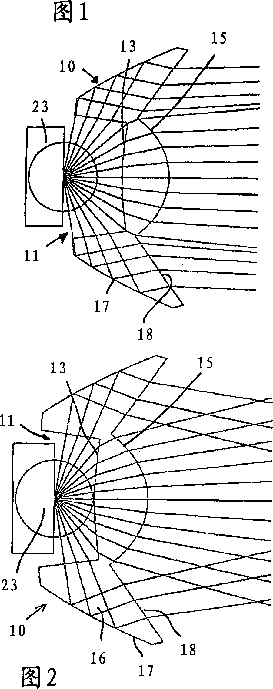
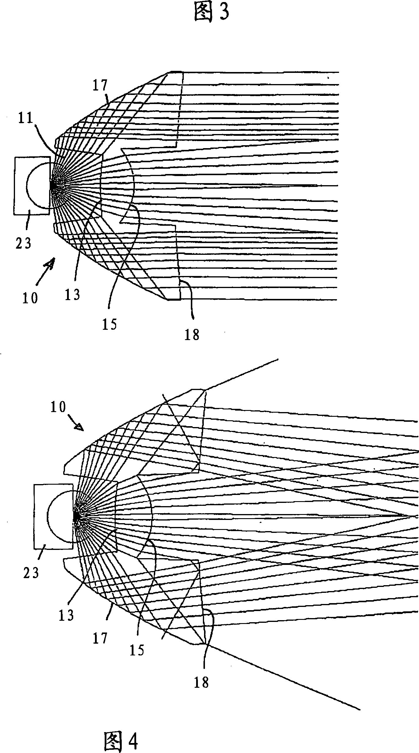
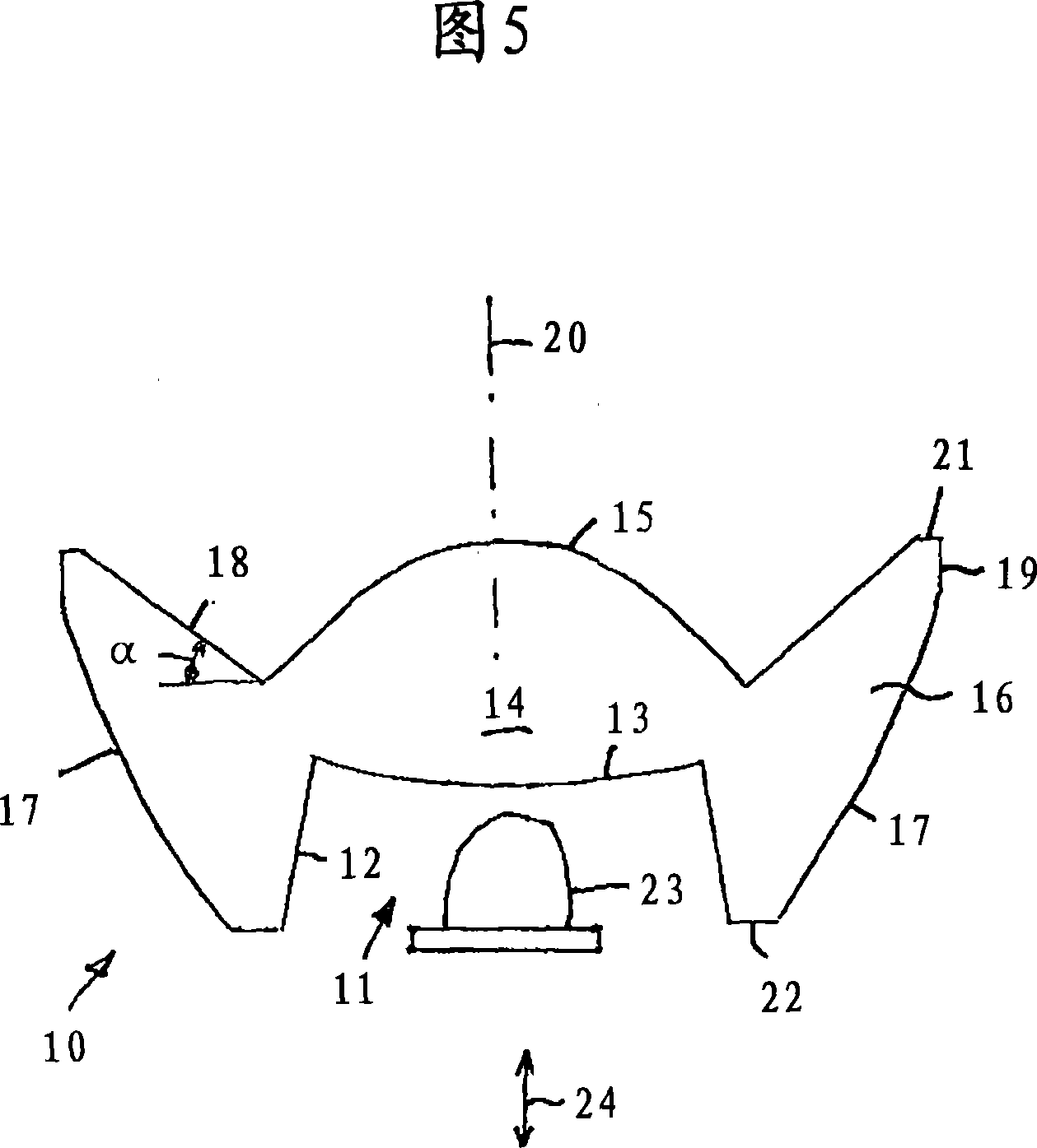
[0021] The secondary optics functioning as a lens body has a rear blind hole-shaped opening 11 which is delimited by a conical peripheral surface 12 and a convexly curved base surface 13 . The base surface 13 is also the light entry surface of the inner condenser lens part 14 which has a convexly curved light exit surface 15 on the front side. The condenser lens part 14 is surrounded by a reflector part 16, which basically passes through the peripheral surface 12 as the light incident surface and an outer shell-shaped peripheral surface 17 as the light completely reflecting surface and a front cone. Shaped light exit surface 18 constitutes. As shown, the mirror part 16 can also have wall sections 19 parallel to the optical axis and additionally edge regions 21 , 22 perpendicular to the optical axis. The overall diameter of the auxiliary optics shown in FIG. 5 can be, for example, 20 mm, 25 mm or 36 mm, for a construction height of 9 mm, 11 mm or 16 mm, respectively. The open...


PUM

PropertyMeasurementUnit
Minimum diameteraaaaaaaaaa
Total heightaaaaaaaaaa

Abstract

The invention relates to an LED illumination module having an LED (23) and a rotationally symmetrical, integral, light-transparent auxiliary optic (10) having an inner converging lens part (14) and an outer reflector part (16). The auxiliary optic (10) has an opening (11) in the form of a blind hole which is arranged at the rear and in which the LED (23) can be displaced longitudinally and axially along the optical axis (20) such that, owing to the displacement, a change in the cone of light from a cone of light having a cone angle < 12° to a cone angle >20° can be produced and, in at least one LED position with respect to the opening (11) of the auxiliary optic (10), an inner region of the cone of light is illuminated homogeneously over a cross-sectional area at right angles to the optical axis (20).

Description

technical field [0001] The invention relates to an LED lighting module comprising an LED and a rotationally symmetrical one-piece light-transmitting auxiliary optics (Vorsatzoptik) with an inner condenser lens part and an outer reflector part and a blind-hole-shaped opening on the back. Background technique [0002] Such LED lighting modules are used, for example, in flashlights. Flashlights with incandescent lamps known according to the prior art currently have a lamp cap that widens conically towards the end face, inside which is arranged a concave reflector, which is usually formed as a parabola, at the focus of which is arranged Incandescent lamps or their helical filaments. An optimum light efficiency is to be preserved by this arrangement. Such concave reflective mirror surfaces may be disadvantageously prone to contamination or the mirror surface may be discolored by corrosion effects, so that the reflection of light becomes weaker. [0003] Flashlights equipped w...

Claims


Application Information

Patent Timeline
IPC IPC(8): F21V7/00F21V5/04F21V14/02F21L4/02
CPCF21V14/025F21V5/045F21V5/006F21L4/027F21V7/0091F21Y2101/02F21Y2115/10
Inventor R·奥波尔卡A·蒂明格
Owner LED LENSER CORP
Why Eureka
Try Eureka