An oxygen sensor and a method utilising it

An oxygen sensor and gas technology, applied in the direction of instruments, scientific instruments, measuring devices, etc., can solve the problem of destroying the organic residual products of the oxygen sensor

Inactive Publication Date: 2007-08-15
PBI-丹山社联合股份有限公司
View PDF0 Cites 2 Cited by
  • Summary
  • Abstract
  • Description
  • Claims
  • Application Information

AI Technical Summary

Problems solved by technology

For example, with roasted and ground coffee, orga

Method used


Image

  • An oxygen sensor and a method utilising it
  • An oxygen sensor and a method utilising it
  • An oxygen sensor and a method utilising it

Examples


Embodiment Construction

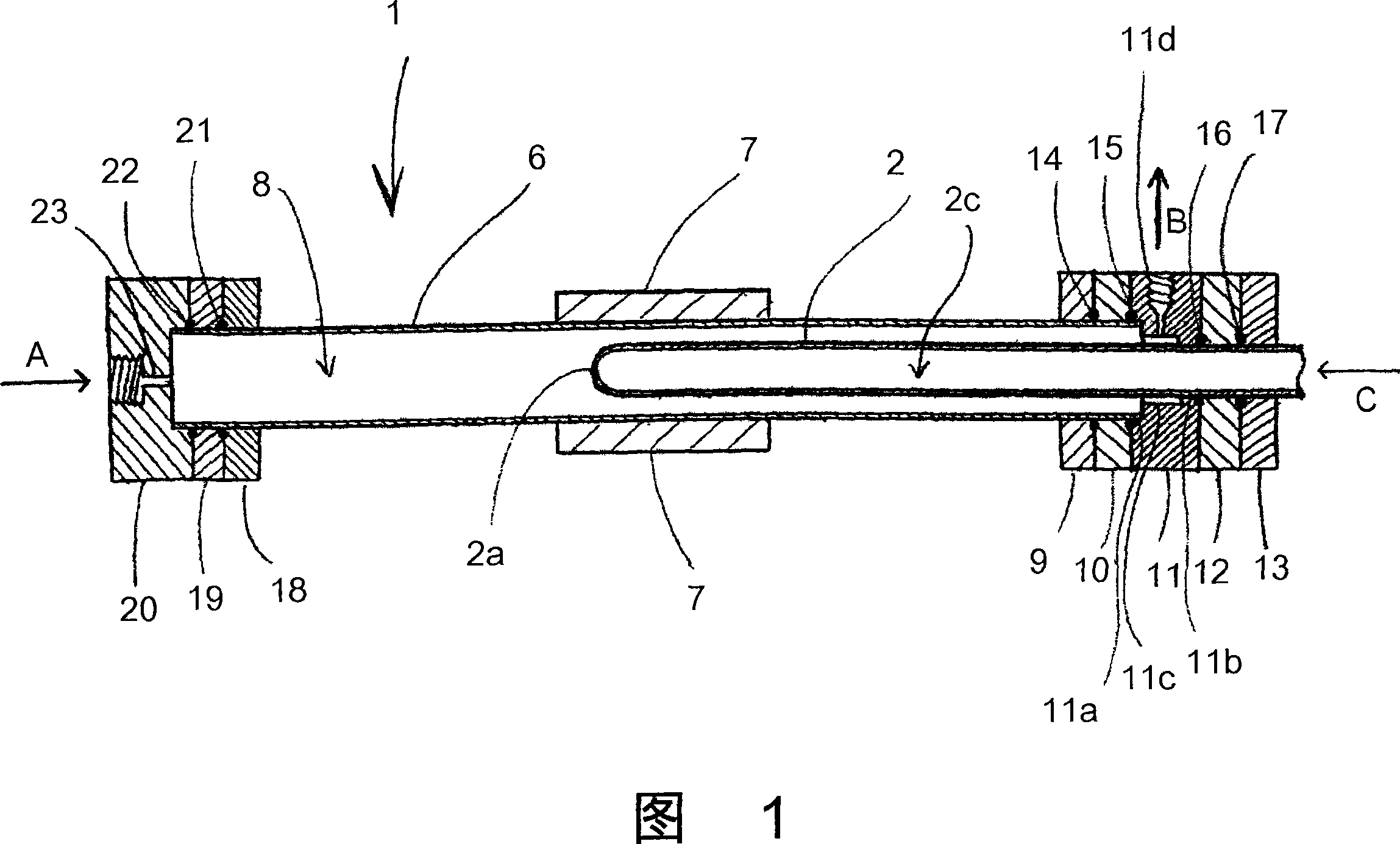
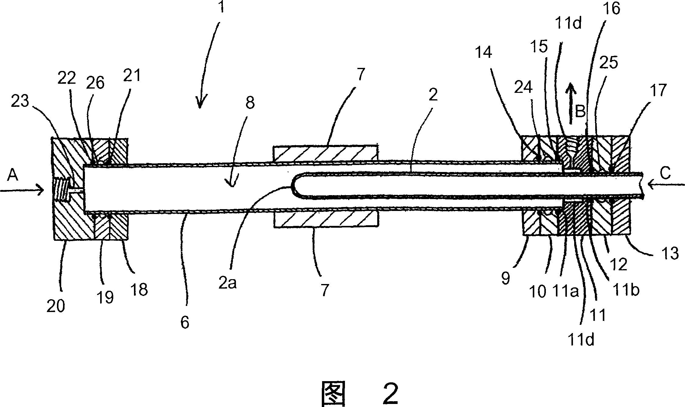
[0038] The two embodiments have a number of features in common, so below the same reference numerals will be used to identify corresponding parts of the two embodiments.

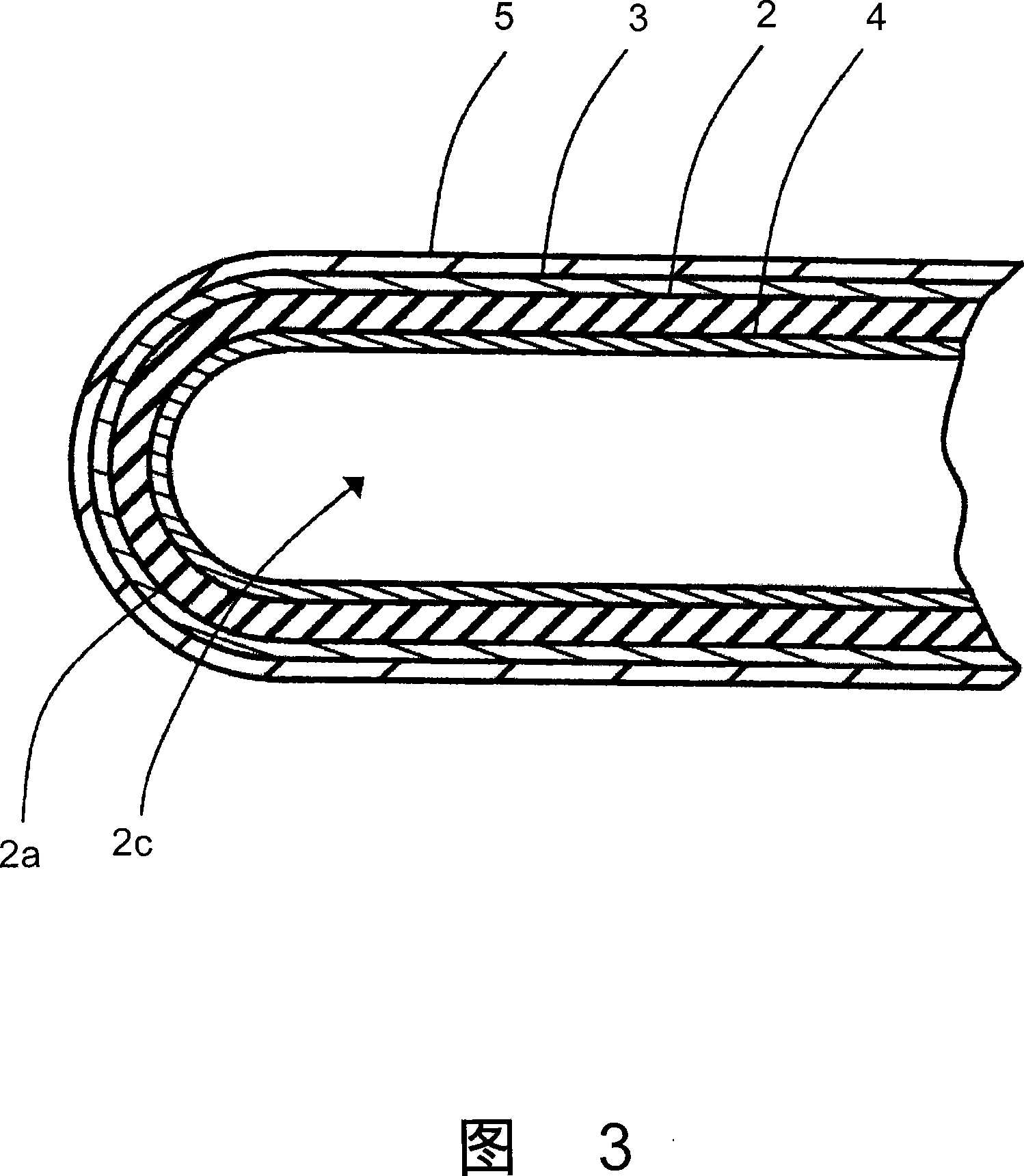
[0039] FIG. 1 schematically shows a section through an oxygen sensor 1 according to the invention. The oxygen sensor comprises a membrane in the form of a first tube 2 . The first tube 2 is basically made of stabilized zirconia (ZrO 2 )production. The first tube 2 is preferably cylindrical, but ends in a hermetically closed end 2a, which is integral with the rest of the tube, while the other end (not shown) is open. The first tube 2 is positioned such that it extends at least partly into the second tube 6, which is also preferably cylindrical. Preferably, the first tube 2 is placed concentrically with the second tube 6, as shown in Figures 1 and 2, that is, the open end of the first tube is located outside the second tube 6, and the closed end 2a is positioned approximately into the second tube half the ...


PUM


Abstract

Use of an oxygen sensor comprising a membrane, preferably in the form of a first tube (2), which is substantially made of zirconium dioxide and has an internal and an external coating (3, 4) of an electrically conductive, catalytic layer. On the electrically conductive, catalytic layer, a porous, preferably ceramic layer (5) is provided. The porous layer (5) is provided on the electrically conductive, catalytic layer (3), which is located at least partially within a second tube (6), made of a gas tight material. The oxygen sensor, which is part of a clamped together structure with O-rings, may be used in a method, in which the measuring gas, especially a reactive measuring gas, is supplied to the external side of the first tube (2).

Description

technical field [0001] The present invention relates to the use of an oxygen sensor comprising a thin film made essentially of stabilized zirconium dioxide, with first and second conductive catalytic coatings on each side of the thin film. Furthermore, the invention relates to a method for determining the oxygen content in a gas and an oxygen sensor comprising a membrane in the form of a first tube substantially made of stabilized zirconium dioxide and at least partially located in a gas-tight material. Inside the second tube, the first tube has a first conductive, catalytic coating on its inner surface and a second conductive, catalytic coating on its outer surface, preferably a porous ceramic coating on the outer conductive, catalytic coating. Background technique [0002] Such oxygen sensors for measuring technical gases are known, for example, from PBI-Dansensor A / S of Ringsted, Denmark. [0003] This well-known oxygen sensor, which has been on the market for more than ...

Claims


Application Information

Patent Timeline
IPC IPC(8): G01N27/407
CPCG01N27/4077G01N27/407G01N27/12
Inventor H·詹森P·富高E·S·索尔伯格K·汉森
Owner PBI-丹山社联合股份有限公司
Why Eureka
Try Eureka