Ultrasonic torsional vibration turning-milling system and method

A torsional vibration and ultrasonic technology, applied in the direction of driving devices, milling machine equipment, milling machine equipment details, etc., can solve the problems of difficult to guarantee machining accuracy, low machining quality, high turning and milling temperature, and achieve easy automatic chip removal, high machining quality, The effect of improving machining accuracy

Inactive Publication Date: 2007-08-22
HANGZHOU DIANZI UNIV
View PDF0 Cites 10 Cited by
  • Summary
  • Abstract
  • Description
  • Claims
  • Application Information

AI Technical Summary

Problems solved by technology

[0007] 1) During the turning and milling process, the impact force is large, and it is difficult to guarantee the machining accuracy;
[0008] 2) The surface is rough and the processing quality is low;
[0009] 3) Turning and milling temperature is higher

Method used


Image

  • Ultrasonic torsional vibration turning-milling system and method

Examples


Embodiment Construction

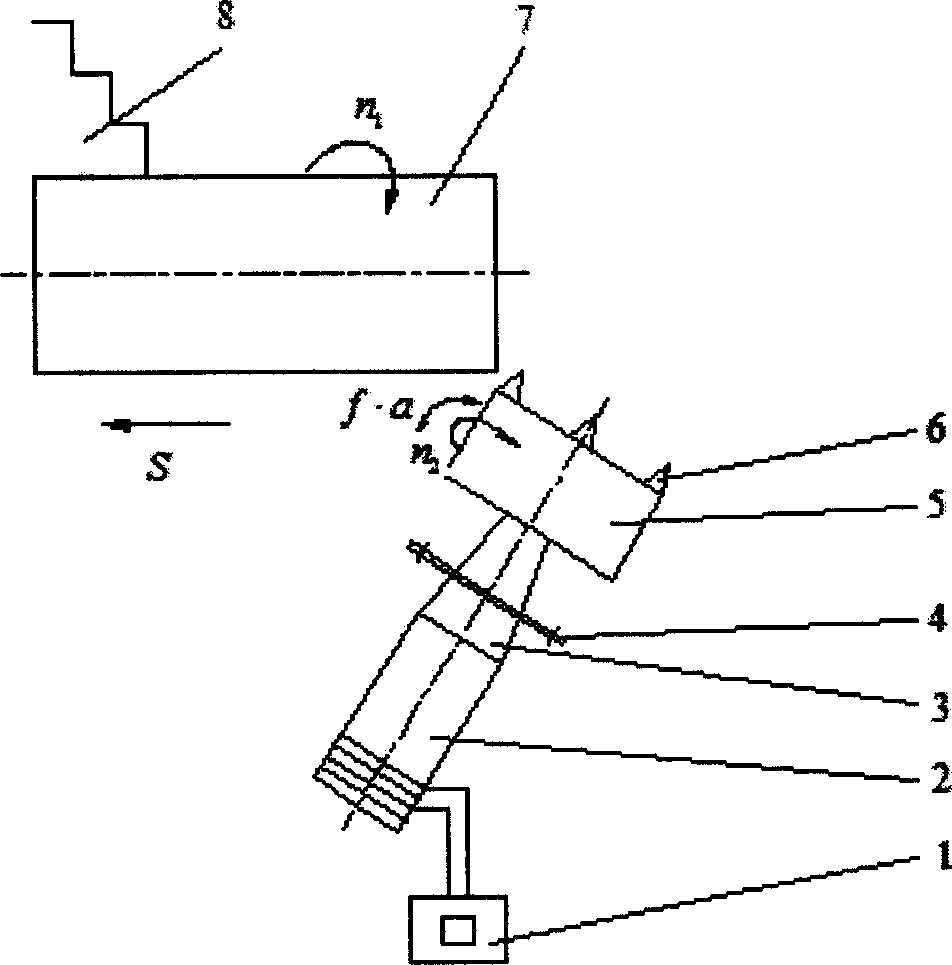
[0025] As shown in the attached figure, the ultrasonic torsional vibration turning and milling system adopts an ultrasonic torsional vibration turning and milling device in the turning and milling system. It has an ultrasonic generator 1, a torsional vibration sandwich piezoelectric transducer 2, a torsional vibration horn 3. Flange plate 4, milling cutter disc 5, cutter teeth 6, frame, torsional vibration sandwich piezoelectric transducer 2 connected to torsional vibration horn 3, milling cutter, milling cutter with milling cutter disc 5, Cutter teeth 6 are arranged on the milling cutter disc, and a flange 4 is arranged on the torsional vibration horn 3, and the flange 4 is connected with the frame.

[0026] The ultrasonic torsional vibration turning and milling method is to realize the cutting of the workpiece by using the synthetic motion of milling cutter rotation, workpiece 7 rotation, milling cutter axial feed, milling cutter radial feed, and milling cutter ultrasonic tor...


PUM

PropertyMeasurementUnit
energy conversion efficiencyaaaaaaaaaa

Abstract

The present invention discloses one kind of ultrasonic torsional vibration turning-milling system and method. In the turning-milling process, the resultant motion of the rotation of the milling cutter, the rotation of the workpiece, the axial feeding of the milling cutter shaft, the radial feeding of the milling cutter and the ultrasonic torsional vibration of the milling cutter is adopted to complete the cutting of the workpiece. The ultrasonic torsional vibration of the milling cutter is generated with ultrasonic torsional vibration devices arranged radially along the workpiece. The present invention has the advantages of easy elimination of scraps, high machining precision, etc.

Description

technical field [0001] The invention relates to a turning method, in particular to an ultrasonic torsional vibration turning and milling system and a method thereof. Background technique [0002] The principle of the turning and milling method is to replace the turning tool with a milling cutter to complete the processing method of intermittent turning motion. In the turning and milling process, the synthetic motion of the milling cutter rotation and the workpiece rotation is used to realize the cutting process of the workpiece, so that the workpiece can meet the use requirements in terms of shape accuracy, position accuracy, surface roughness and residual stress. [0003] Turning and milling processing includes four basic movements of milling cutter rotation, workpiece rotation, milling cutter axial feed and radial feed. The rotary motion of the milling cutter is the main motion. The cutting speed is determined by the rotation speed of the milling cutter and the rotation ...

Claims


Application Information

Patent Timeline
Patent Type & Authority Applications(China)
IPC IPC(8): B23B1/00B23C3/00B23Q5/02
Inventor 张云电喻家英余芳
Owner HANGZHOU DIANZI UNIV
Why Eureka
Try Eureka