Heat exchanger with temperature-controlled valve

A technology of heat exchangers and temperature sensors, applied in heat exchange equipment, indirect heat exchangers, heat exchanger types, etc., can solve the problem of slow temperature detection

Active Publication Date: 2007-08-22
EP TECH +1
View PDF3 Cites 12 Cited by
  • Summary
  • Abstract
  • Description
  • Claims
  • Application Information

AI Technical Summary

Problems solved by technology

The most common cause of this problem is

Method used


Image

  • Heat exchanger with temperature-controlled valve
  • Heat exchanger with temperature-controlled valve

Examples


Embodiment Construction

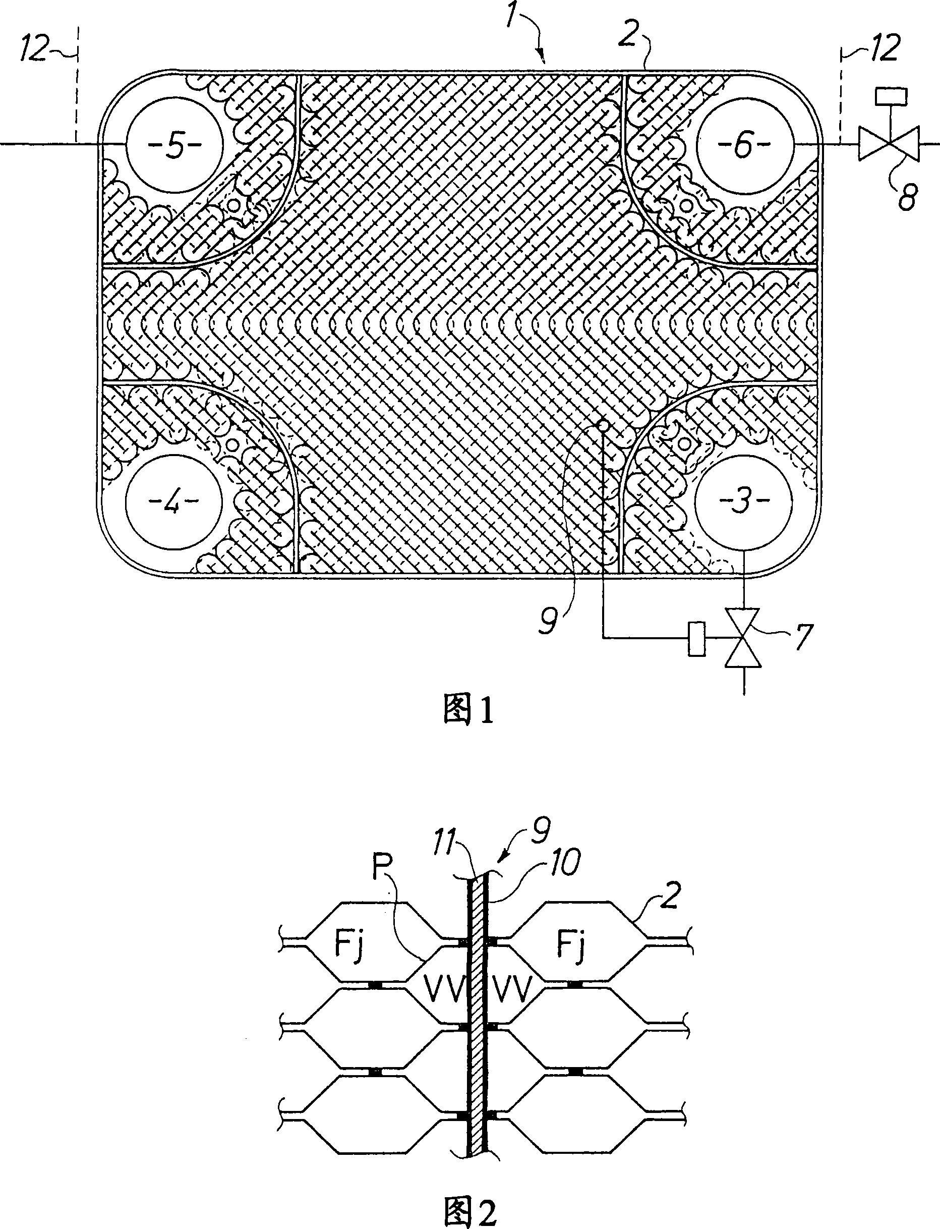
[0012] Plate heat exchangers are well known devices for exchanging heat between two different media. Plate heat exchangers are used in many different applications, and although the invention has been specifically developed as a heat exchanger for supplying hot water using district heating, the invention is not limited to any particular application. The present invention is most suitable for various all-brazed plate heat exchangers. In other words, the heat exchanger comprises a plate with a pattern of grooves with inlet and outlet connections for the two media. These boards are placed in an assembly and brazed together to form a unit. Separate channels for the two media circulating countercurrently to one another are formed between the exchangeable plate pairs. This technique is well known and therefore will not be described in detail here.

[0013] Figure 1 is a schematic diagram of a heat exchanger for heating water with hot water from a district heating network. The hea...


PUM

PropertyMeasurementUnit
Heat of fusionaaaaaaaaaa

Abstract

The invention relates to a heat exchanger with a temperature sensor and especially a heat exchanger usable for heating hot water using district heating water. The heat exchanger (1) contains plates (2) placed in a pack and brazed together so that 5 separate channels for first (Fj) and second (VV) media are formed between alternate pairs of plates; two pairs of connections for inlet (3) and outlet (4) for the first medium and inlet (5) and outlet (6) for the second medium, respectively; and a temperature sensor (9) connectable to a valve (7) to control supply of the first medium through the heat exchanger. The first medium is intended to supply heat to 10 the second medium. The temperature sensor (9) is placed through a number of plates and in heat conducting contact with them such that the temperature sensor controls the first valve.

Description

technical field [0001] The present invention relates to a heat exchanger with a temperature sensor, and in particular to a heat exchanger usable for heating hot water using district hot water. The present invention provides a heat exchanger for connection to a valve which can be quickly opened and closed by proper positioning and connection of a temperature sensor controlling the valve. Background technique [0002] As we all know, heat exchangers can be used to heat hot water. A particular problem in this respect is that the hot water supply from the district heating system has to be cut off quickly when the hot water tapping is interrupted. Otherwise there is a risk that the water will overheat and in particular cause scalding of other things. Document EP 608195 discloses a solution to this problem. A temperature sensor is placed in the dippipe, which is in contact with the water in both the district heating and hot water circuits. However, since the sensor is located ...

Claims


Application Information

Patent Timeline
IPC IPC(8): F28D9/00F28F27/00F24D10/00F24D19/10F28F
CPCF24D19/1069F24D10/00F28D9/005F28F27/00Y02E20/14Y02B30/17
Inventor 拉尔斯·佩尔松
Owner EP TECH
Why Eureka
Try Eureka