Methods of measuring and compensating cutting size on chamfering machine of sheet material

A technology of chamfering device and measuring method, which is applied in the direction of automatic control device, metal processing equipment, measuring/indicating equipment, etc., can solve the problems of increasing equipment burden or work burden, time-consuming, error increase, etc., and achieve the reduction of measurement costs Effect of time required and workload

Inactive Publication Date: 2007-08-29
NAKAMURATOME SEIMITSU IND
View PDF0 Cites 21 Cited by
  • Summary
  • Abstract
  • Description
  • Claims
  • Application Information

AI Technical Summary

Problems solved by technology

[0009] However, in the above-mentioned conventional methods, since the measurement of the processing size is carried out manually, there are the following problems: the operator must have skilled skills; there may be measurement errors due to carelessness and misreading; It takes time to calculate the correction value of the table angle and tool position by measuring the value; the operator needs to manually input the calculated correction value into the controller of the chamfering device, which may cause input errors, etc. Wait
In addition, as a problem specific to the chamfering device, the following problem also arises: with the increase in area and thickness of the glass substrate as the workpiece, the substrate processed for the test and the substrate for sampling inspection are separated from the chamfering device. The difficulty of taking it out and setting it on the detection device increases; and, with the enlargement of the workbench, the error of the p

Method used


Image

  • Methods of measuring and compensating cutting size on chamfering machine of sheet material
  • Methods of measuring and compensating cutting size on chamfering machine of sheet material
  • Methods of measuring and compensating cutting size on chamfering machine of sheet material

Examples


Embodiment Construction

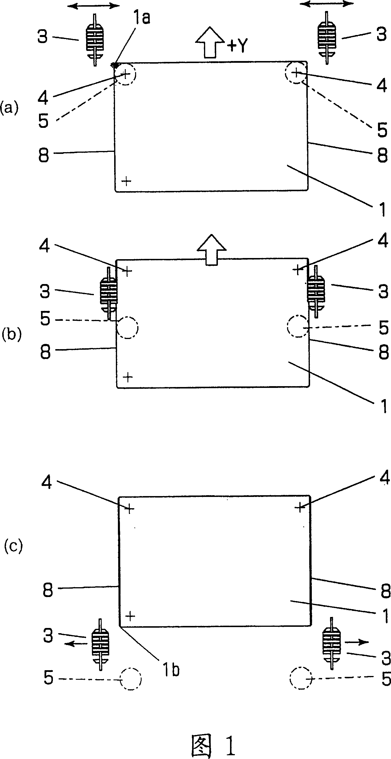
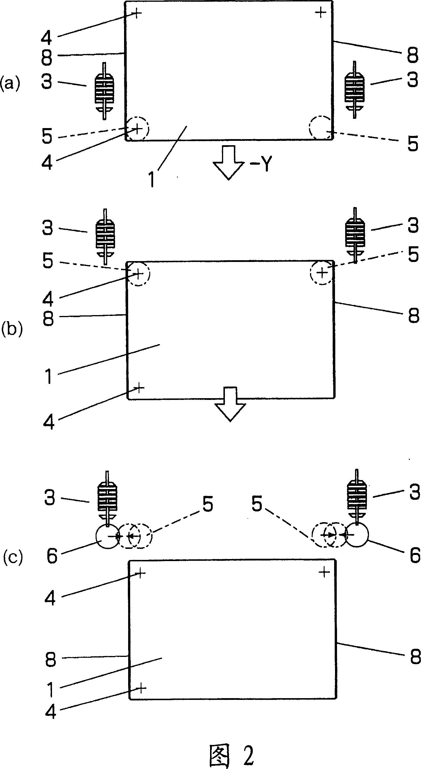
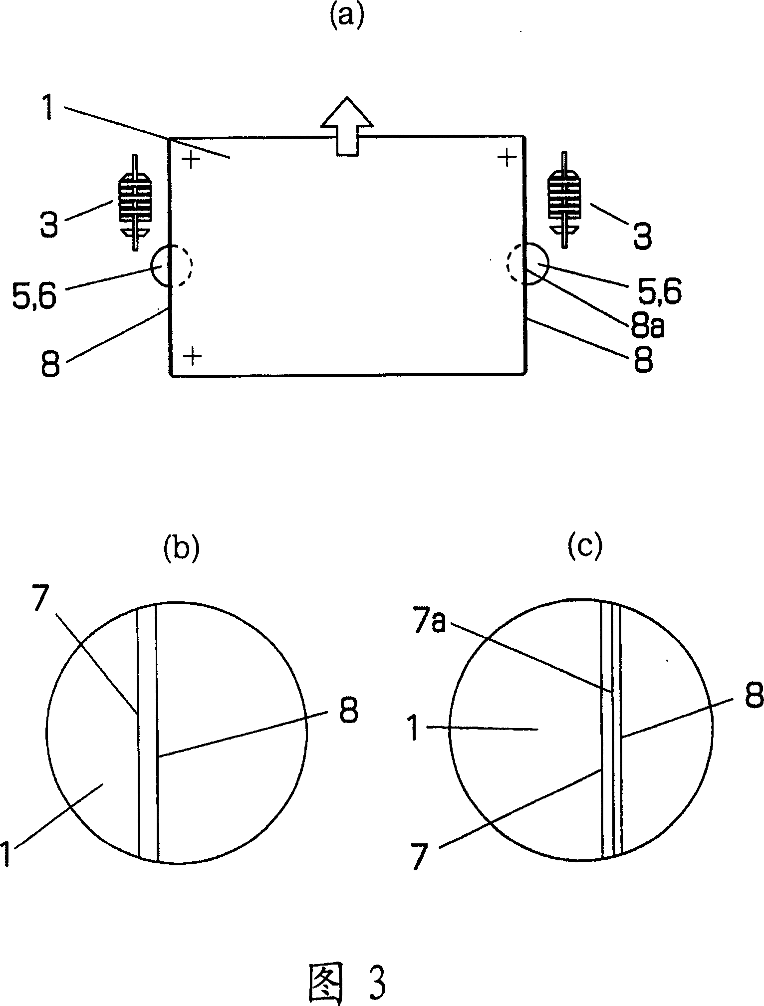
[0031] Hereinafter, embodiments of the present invention will be described with reference to the drawings. As shown in FIG. 7 , on the chamfering device implementing the method of the present invention, there are lower cameras 6 , 6 for reading the chamfering lines of the lower surfaces of opposite edges of the processed plate 1 . The workbench 2, the tool 3, the camera (upper camera) 5 for reading the positioning mark, and the installation structure of these parts and the positioning mark 4 provided on the board 1 are all the same as conventional ones. The upper and lower cameras 5, 6 and the tool 3 are loaded on the same supporting platform (not shown in the figure), and can move freely along the width direction respectively, and the positional relationship between the tool 3 and the cameras 5, 6 in the feeding direction remains unchanged . The lower cameras 6, 6 move to the position directly below the upper cameras 5, 5 only when reading the processing size described later...


PUM


Abstract

The invention relates to a method for measuring and correcting chamfer size of rectangle glass basal edge. It is not necessary to detach the workpiece from chanfer device, therefore the finish size is automatically detected and the position of worktable and tool of chanfer device based on the detected value. After the positioning mark is set on the position of three acmes of right triangle formed on the board and the board and lateral border parrallel to feed direction are processed, in the first measuring procedure, the board is transfered towards returning direction and one camera of two camera reads two marks set on the feed direction to detect difference of two marks at the position perpendicular to feed direction. In the second measuring procedure, after the camera is moved to the position for reading the lateral border, the board is feeded and the finish size of lateral border is detected by the two camera. In addition, the angle of worktable and the allowance of tool height are calculated based on the detecting result.

Description

technical field [0001] The present invention relates to a method of measuring and correcting processing dimensions in a chamfering device used for processing the edges of rectangular glass substrates such as display screens, that is, to a method of measuring and correcting processing dimensions of a plate as an object of test processing and sampling inspection. It is a method to process dimensions, perform automatic measurement, and correct the positions of the table and tools of the chamfering device based on the measured values. Background technique [0002] A chamfering device for a glass substrate is a device that chamfers or rounds sharp ridges and corners generated on the edge of a glass substrate cut by cutting or the like with a tool (usually a grinding wheel). As shown in FIG. 8 , generally, such a chamfering apparatus has a worktable 2 that absorbs a glass substrate 1 with negative pressure, and tools 3 provided on both sides of the workbench. The worktable 2 can ...

Claims


Application Information

Patent Timeline
IPC IPC(8): B24B9/10B24B49/12
CPCB23Q15/24B23Q17/2233B24B9/10B24B49/02
Inventor 坂下浩之齐田一
Owner NAKAMURATOME SEIMITSU IND
Why Eureka
Try Eureka