
System for tracking running state of underground plunger for gas production and working method thereof

A technology of running status and tracking system, which is applied in earthwork drilling, wellbore/well components, measurement, etc. It can solve the problem that the stuck depth cannot be calculated through the model, and the optimized production and predicted value of the plunger gas lift production well cannot be realized. The problem of discrepancy with the actual value and other problems, to achieve the effects of direct parameter collection and measurement tools and means, shortening invalid production time, and improving operating efficiency

Inactive Publication Date: 2012-06-27
PETROCHINA CO LTD
View PDF6 Cites 9 Cited by
  • Summary
  • Abstract
  • Description
  • Claims
  • Application Information

AI Technical Summary

Problems solved by technology

At present, pressure parameters such as gas well flow pressure, casing pressure, and surface production pipeline pressure can be obtained through pressure sensors, which can be realized by using existing mature technologies, while other production parameters, such as liquid surface depth, liquid column height, and plunger operating status The parameters (the current running position of the plunger, the running speed and acceleration of the plunger) have not yet had good technical means for effective real-time monitoring and collection, and the truly optimized production of the plunger gas lift production well cannot be realized.
The existing plunger gas lift production management is mainly based on theoretical models. The model is used to predict the time when the plunger reaches the bottom of the well and the time when the plunger starts to enter the dynamic liquid surface. Due to the defects of the model itself, there will be a discrepancy between the predicted value and the actual value. big discrepancy
For example, the model predicts that it will take 2.5 hours for the plunger to fall to the bottom of the well, but it only takes 1 hour to return to the bottom of the well. Since the well has not been in production for a long time, the liquid above the plunger is accumulating more and more, and it takes 2.5 hours to pass When the on-off valve is opened and the plunger goes up, the running speed is too slow due to the heavy liquid column, and even before reaching the wellhead, the plunger stops running due to the drop in gas pressure consumption
In another case, the time for the plunger to fall to the bottom of the well predicted by the model was too short, causing the surface switch valve to open before the plunger entered the liquid column, and the plunger began to move upward without lifting any liquid, causing the system to invalid operation of
In addition, it is also very important to master the running speed of the plunger. If the upward speed of the plunger is too fast and not detected and controlled in time, it may cause damage to the wellhead equipment
At the same time, there are many parameter theoretical models that cannot be predicted. For example, when the plunger is stuck in the oil pipe during operation, the stuck depth cannot be obtained through the model, and other means are needed to judge the actual position of the stuck point.
[0005] For the determination of the dynamic liquid level, although there is wellhead acoustic wave measurement technology, this technology has certain limitations. Because there is no obvious interface between the gas phase and the liquid phase in the wellbore, sometimes there will be foam segments, and these foams will also Reflecting sound waves, which will make the measurement results inaccurate, the measured fluid level is higher than it actually is, optimization based on wrong dynamic level parameters will lead to wrong switching valve opening and closing times
[0006] The patents on plunger gas lift that have been applied for so far involve the mechanical structure, and do not involve the direct measurement of plunger operating parameters, and the dynamic liquid level measurement technology is used in pumping wells and other artificial lift wells. The plunger gas lift is used directly on the well

Method used


Image

  • System for tracking running state of underground plunger for gas production and working method thereof
  • System for tracking running state of underground plunger for gas production and working method thereof
  • System for tracking running state of underground plunger for gas production and working method thereof

Examples


Embodiment Construction

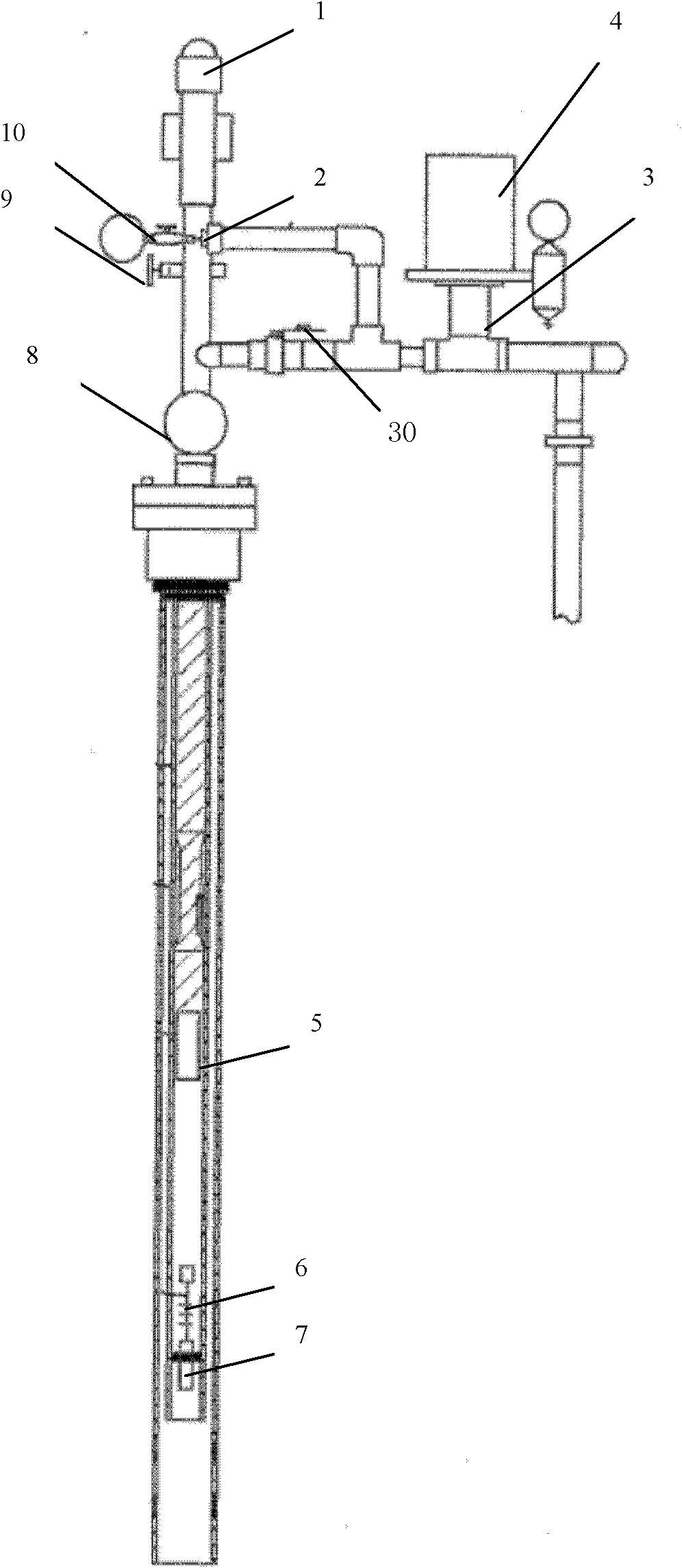
[0028] The present invention proposes a plunger downhole positioning and running state tracking system. The system includes a ground monitoring subsystem. The ground monitoring subsystem collects the acoustic pulse signal transmitted in the oil pipe in real time, and obtains the plunger operating parameters after processing and analyzing. To obtain the running status of the plunger in real time. At the same time, the invention also proposes a plunger downhole positioning and running state tracking method. The method is to collect and measure the acoustic pulse signal transmitted in the tubing in real time to obtain plunger operating parameters to identify the plunger operating state.

[0029] Preferably, the ground monitoring subsystem includes a plunger operation processing module, a ground display device, a ground system power supply, a ground acoustic wave transmitter, and a ground acoustic wave receiver; wherein, the plunger operation processing module is composed of other ...


PUM


Abstract

The invention discloses a system and method for positioning a plunger and tracking the running state of the underground plunger. The system comprises a ground monitor subsystem and a plunger monitor subsystem. The plunger monitor subsystem is controlled by the ground monitor subsystem. The ground monitor subsystem collects sonic pulse signals transmitted from a pipeline in real time and processes and analyzes the signals to obtain plunger operation parameters so as to obtain the plunger running state in real time. A combination of a shock-absorbing spring and a pressing cap is respectively arranged at both ends of the plunger monitor subsystem. The technology for positioning the plunger and tracking the running state of the underground plunger provided by the invention overcomes the inherent deficiencies of conventional mathematical model based plug running state predicting mode, provides real time and more direct parameter collection, measuring tools and means, shortens the invalid production time of the plunger, improves the running efficiency of the system, prolongs the trouble-free production period of a plunger lifting system and is beneficial for improving the individual well producing rate of the gas well and stabilizing the yield of the gas well and improving the economical efficiency.

Description

technical field [0001] The invention relates to the technical field of gas recovery in oil and gas fields, and mainly relates to a wellbore production parameter acquisition and measurement system that provides management and production optimization basis for the production system of natural gas well drainage and gas recovery operations. Background technique [0002] With the increasing demand for clean energy in the national economy, the proportion of natural gas consumption is increasing year by year, and the development and utilization of natural gas resources are also being paid more and more attention. In recent years, the large-scale commercial development of unconventional natural gas resources has changed the pattern of the world natural gas market. With the improvement of gas field recovery, many gas wells have entered the stage of low pressure and low single well production. The flow rate of the gas well is too low to reach the critical liquid-carrying flow rate of...

Claims


Application Information

Patent Timeline
IPC IPC(8): E21B47/14
Inventor 沈泽俊童征郑立臣郝忠献钱杰王全宾黄鹏李明丁爱芹
Owner PETROCHINA CO LTD
Learn More