Paper tray unit

A tray and paper conveying technology, which is applied in the direction of object separation, pile separation, function indication, etc., can solve the problems of unoptimized space saving and large height of ADF73, and achieve the effect of space saving and height suppression

Inactive Publication Date: 2007-08-29
MURATA MASCH LTD
View PDF0 Cites 4 Cited by
  • Summary
  • Abstract
  • Description
  • Claims
  • Application Information

AI Technical Summary

Problems solved by technology

Therefore, the overall height of the ADF 73 becomes large, which is not preferable from the viewpoint of saving space.

Method used


Image

  • Paper tray unit
  • Paper tray unit
  • Paper tray unit

Examples


Embodiment Construction

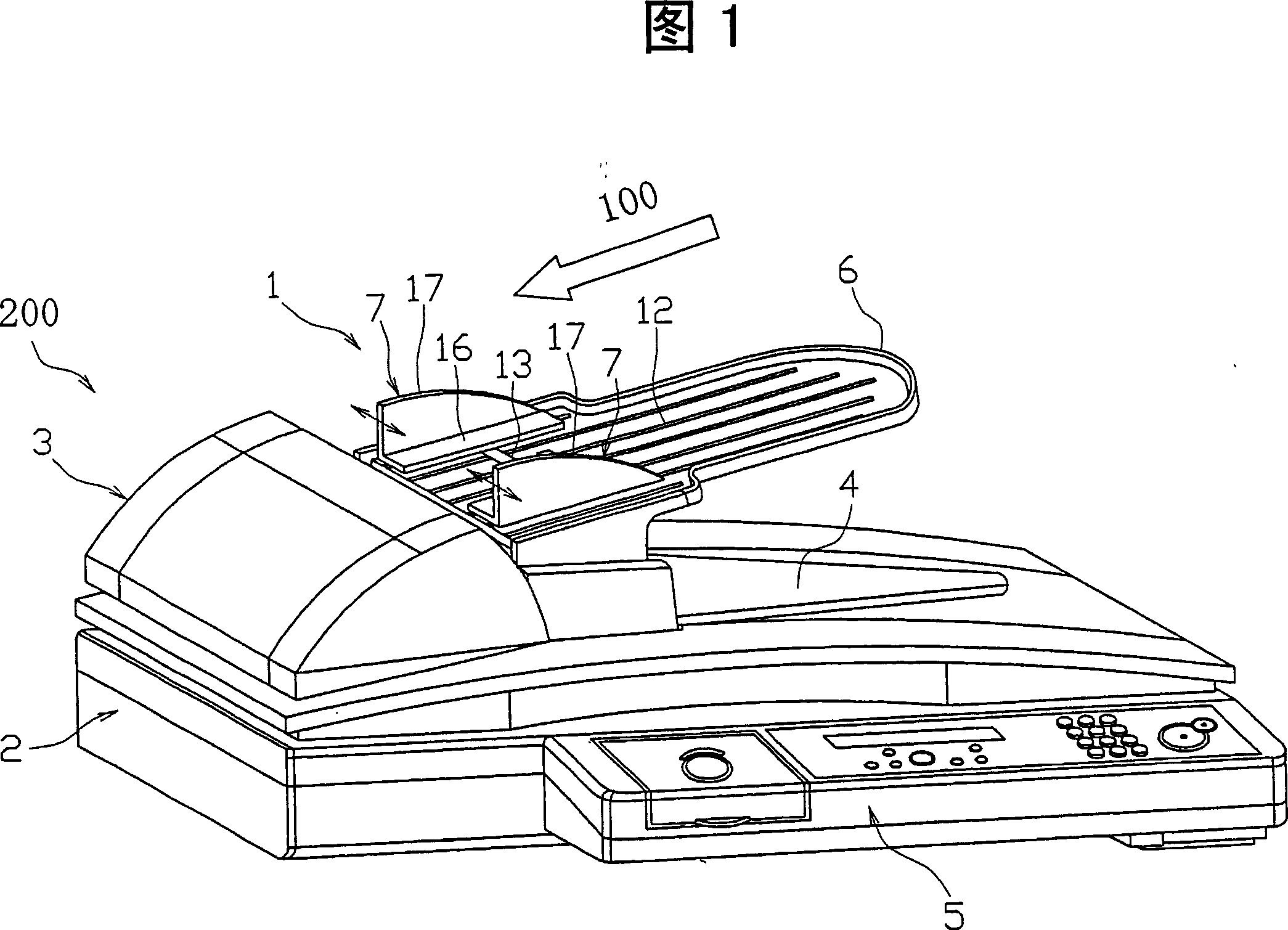
[0021] Hereinafter, a document tray unit according to an embodiment of the present invention will be described based on the drawings. FIG. 1 is a schematic perspective view showing the appearance of an image reading apparatus 200 including a document tray unit 1 according to the first embodiment. The image reading device 200 is provided on top of a copy-facsimile complex machine or the like, and is used to read image information of a document to be copied or sent by facsimile. The image reading device 200 includes a device main body 2 in which an image reading unit (not shown) is accommodated in a hollow casing, an ADF 3 arranged on the upper surface of the device main body 2, and an ADF 3 for placing the image reading unit to be read. A document tray unit (paper tray unit) 1 for a document (paper) to be picked up, a paper output tray 4 for storing a document that has been read, and a front surface of the device main body 2 provided on the front surface of the image reading de...


PUM


Abstract

The object of the invention is to a paper tray unit includes a paper size sensor which is attached to a paper tray and determines a paper size in a paper width direction by detecting a position of a paper width guide. In the paper tray unit, a movable member moves in a paper feed direction accompanying movement of the paper width guide. The position of the paper width guide is detected by the paper size sensor detecting or not detecting the movable member.

Description

technical field [0001] The present invention relates to a paper tray unit for placing paper to be supplied by a paper feeding path, and more particularly to a paper tray unit movably provided on its surface perpendicular to the paper feeding direction for positioning the paper in the width direction A paper tray unit is provided with a paper size sensor for detecting the width direction size of the paper by detecting the position of the paper width guide on the back of the guide part. Background technique [0002] Many scanners, facsimile machines, copiers, and the like are equipped with an image reading device for reading image information of a document. As one of the image reading methods of the image reading device, there is a sheet-feed method in which images are read while sequentially feeding a plurality of originals. This sheet passing method is mainly realized by an automatic document feeder (hereinafter referred to as "ADF"). FIG. 8 is a schematic longitudinal sec...

Claims


Application Information

Patent Timeline
IPC IPC(8): B65H1/00B65H1/04
CPCB65H2511/12B65H2553/61B65H1/04B65H2553/412B65H2403/513B65H2220/09B65H2511/20B65H2801/06B65H2801/39B65H2220/03B65H2220/01B65H2220/11
Inventor 能势佳孝川村敏广
Owner MURATA MASCH LTD
Why Eureka
Try Eureka