Relay with reduced leakage current

一种继电器、漏电路径的技术,应用在电磁继电器、继电器、电磁继电器详细信息等方向,能够解决发生漏电流等问题,达到减小漏电流、漏电路径延长、延长漏电路径的效果

Active Publication Date: 2007-08-29
TYCO ELECTRONICS AUSTRIA
View PDF0 Cites 0 Cited by
  • Summary
  • Abstract
  • Description
  • Claims
  • Application Information

AI Technical Summary

Problems solved by technology

This causes a leakage current to occur between the magnetic system and the contact system of the electromagnetic relay

Method used


Image

  • Relay with reduced leakage current
  • Relay with reduced leakage current
  • Relay with reduced leakage current

Examples


Embodiment Construction

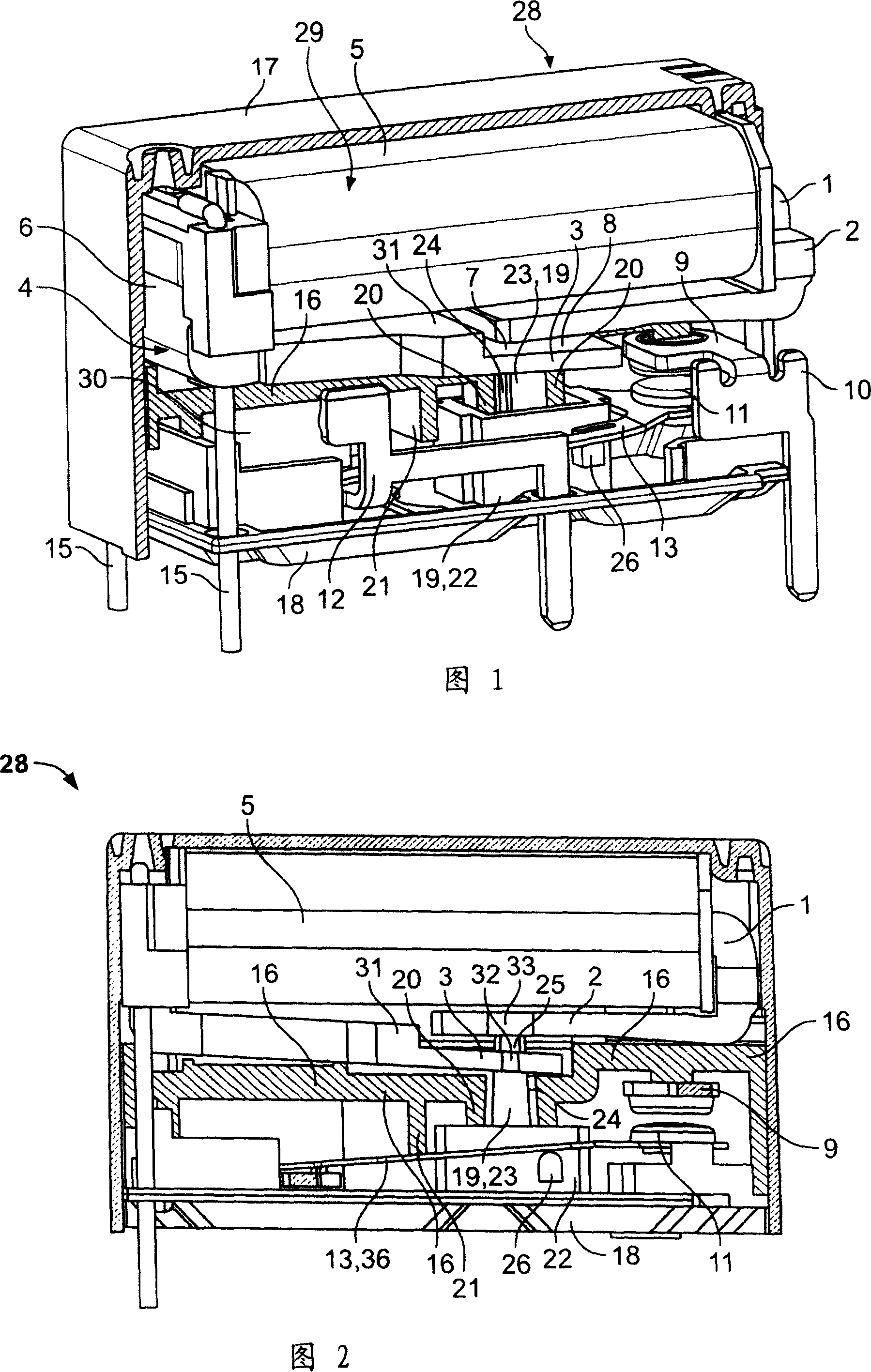
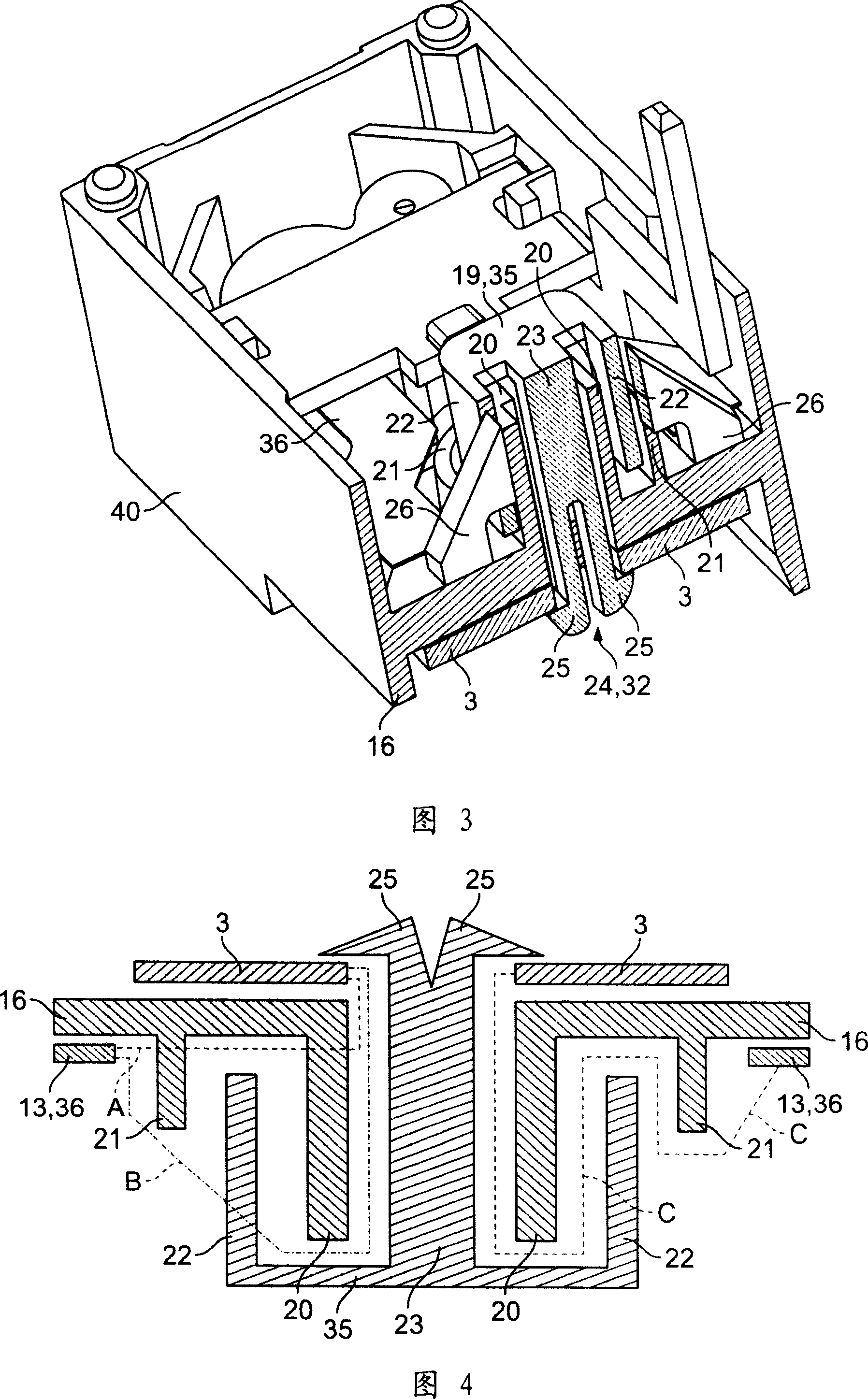
[0025] FIG. 1 shows a partially cutaway perspective view of a relay 28 with a magnetic system 29 and a contact system 30 . The magnetic system 29 and the contact system 30 are separated from each other by the base plate 16 . The magnetic system 29 is positioned on the upper side of the base plate 16 and the contact system 30 is positioned on the bottom side of the base plate 16 . The magnetic system 29 is in active contact with the contact system 30 via an actuator 19 which is guided through the opening 24 of the base plate 16 . Because of the small design and insignificant thickness of the base plate 16 , there is a risk of leakage currents developing between the contact system 30 and the magnetic system 29 . In order to reduce this leakage current, the substrate 16 has a first wall 20 formed on the bottom side of the substrate 16 which surrounds the opening 24 . Furthermore, in a further embodiment, the base plate 16 has a second wall 21 at a distance from the first wall 2...


PUM


Abstract

The invention relates to a relay (28) which includes a housing (40), a magnetic system (29) with an armature (3), a contact system (30) with a movable second contact (11) and a first contact (9). A base plate (16) is located between the magnetic system and the contact system. An actuator (19) is guided through an opening (24) of the base plate from a side of the armature to a side of the contact system and is in active contact with the armature and the contact system. The second contact is moved by the armature via the actuator to change a switch position of the contacts. A wall (20, 21) protrudes from the housing and is located between the opening and the magnetic system or between the opening and the contact system so that a leakage path for an electrical leakage current between the contact system and the magnetic system is extended by the wall.

Description

technical field [0001] The invention relates to a relay comprising a base plate; a magnetic system, an armature, a contact system with a movable second contact and a first contact, wherein the base plate is positioned between the magnetic system and the contact system, Therein an actuator is provided which is guided through an opening in the base plate from the side of the magnetic system to the side of the contact system, wherein the actuator is in movable contact with the armature and the second contact, wherein the second contact The point can be moved by the armature through operation of the actuator, thereby changing the switching position of the first and second contacts. Background technique [0002] Electromagnetic relays are used in the most diverse fields of technology, especially in automotive engineering. Further developments in relays increased the power as well as the current voltage to be switched. In addition, depending on the field of use, the design size ...

Claims


Application Information

Patent Timeline
Patent Type & Authority Applications(China)
IPC IPC(8): H01H50/02H01H50/16H01H50/54
CPCH01H50/026H01H2050/044
Inventor 鲁道夫·米克尔
Owner TYCO ELECTRONICS AUSTRIA
Why Eureka
Try Eureka