
Prism lens and back-light molding set therewith

一种背光模组、棱镜片的技术,应用在棱镜、光导、光学等方向,能够解决出射光亮度降低、大光线传输损失、难满足液晶显示面板亮度要求等问题,达到提高亮度、缩小光线分布、避免光传输损失的效果

Inactive Publication Date: 2007-09-05
HONG FU JIN PRECISION IND (SHENZHEN) CO LTD +1
View PDF0 Cites 5 Cited by
  • Summary
  • Abstract
  • Description
  • Claims
  • Application Information

AI Technical Summary

Problems solved by technology

However, the arrangement of the scattering layer 116 leads to a large light transmission loss, thereby reducing the brightness of the outgoing light, so it is difficult to meet the brightness requirements of the liquid crystal display panel

Method used


Image

  • Prism lens and back-light molding set therewith
  • Prism lens and back-light molding set therewith
  • Prism lens and back-light molding set therewith

Examples


Embodiment Construction

[0016] The prism sheet of the present invention and the backlight module using the prism sheet will be further described in detail below with reference to the drawings and multiple embodiments.

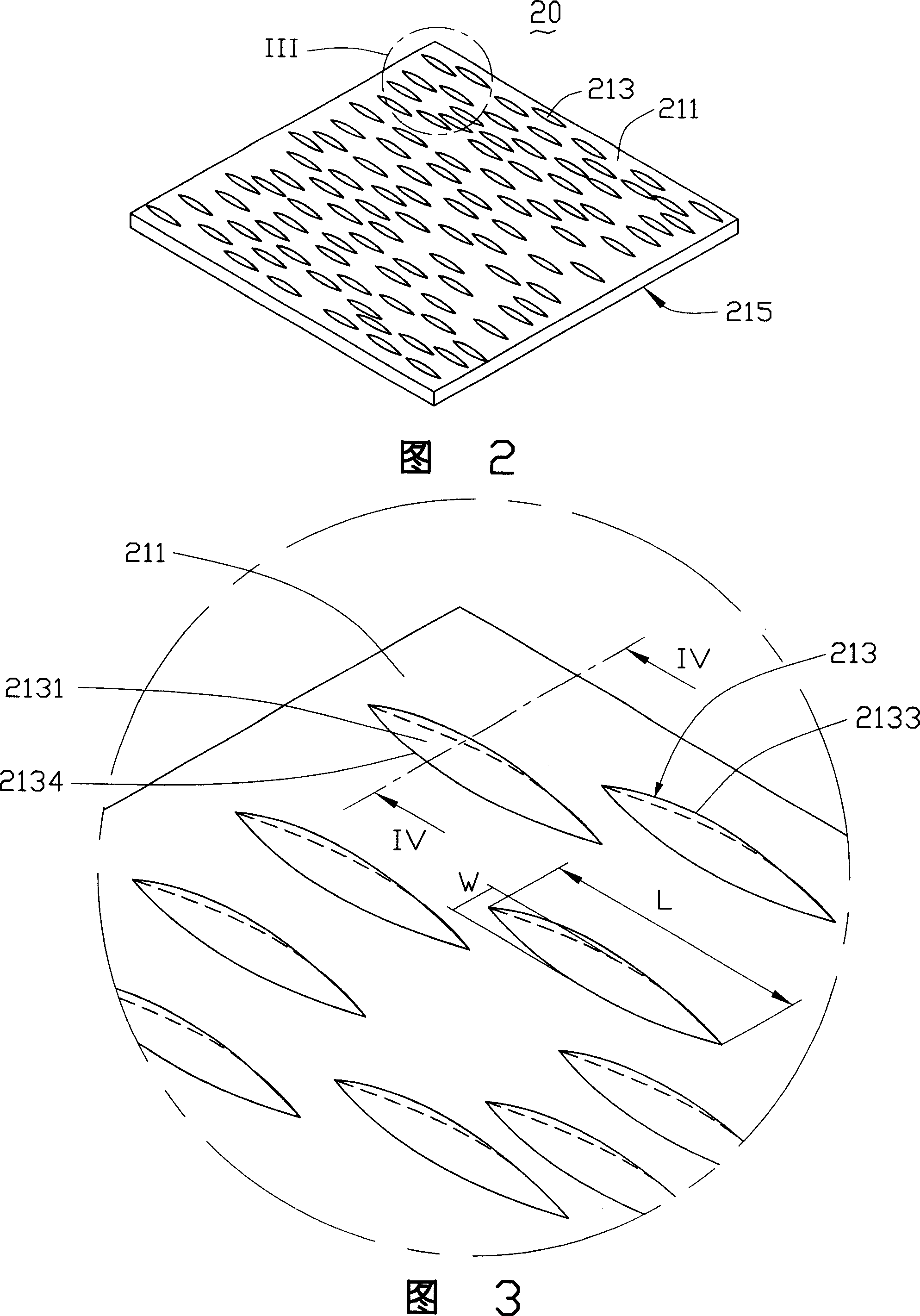
[0017] Please refer to FIG. 2 , which is a preferred embodiment of the prism sheet of the present invention. The prism sheet 20 includes a light incident surface 211 , a light exit surface 215 opposite to the light incident surface, and a plurality of micro protrusions 213 formed on the light incident surface 211 . The light emitting surface 215 is a flat surface.

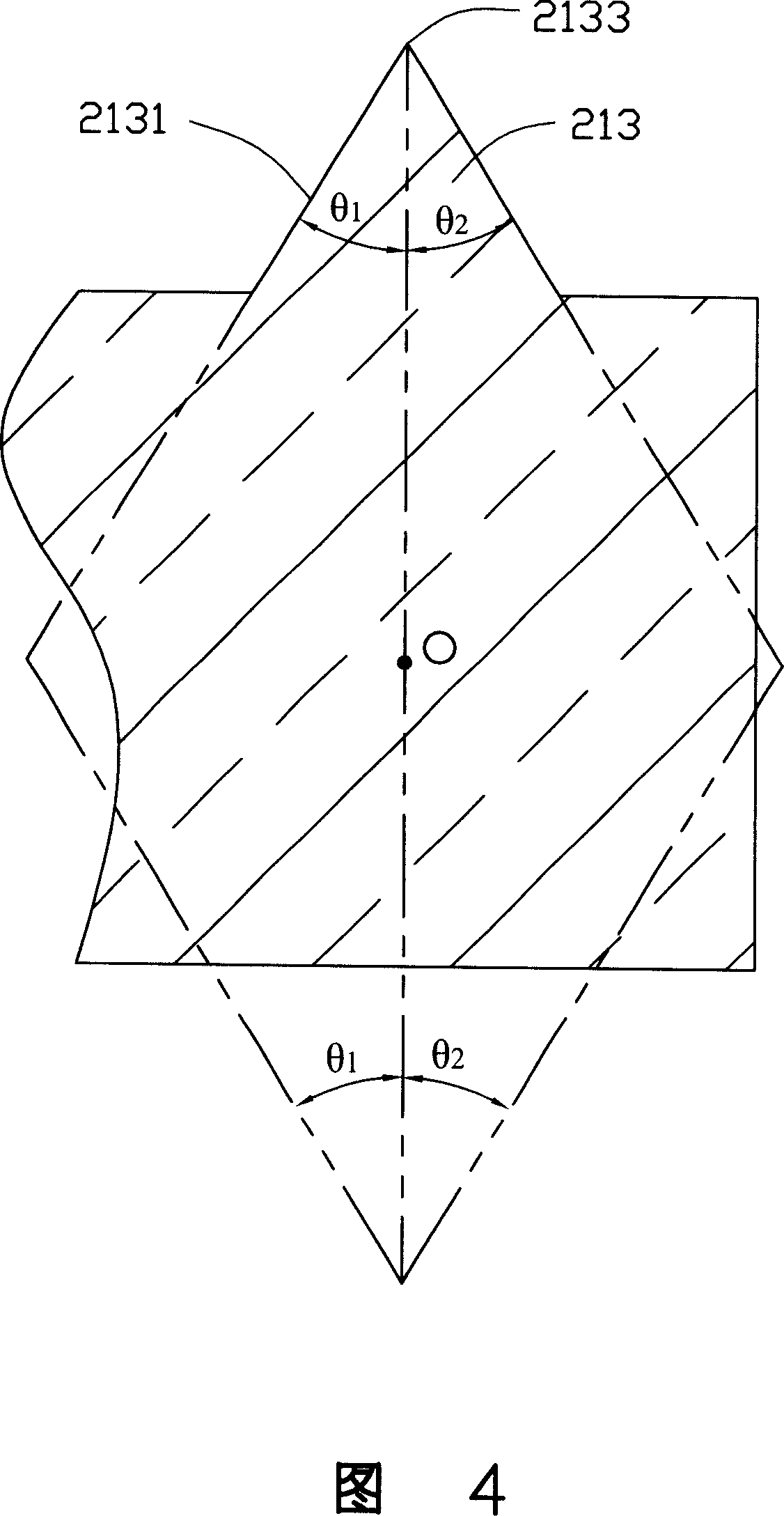
[0018] Please refer to FIG. 3 and FIG. 4 , each micro-protrusion 213 includes two convex sides 2131 and an arc top line 2133 . The circle where the arc top line 2133 is located intersects the light incident surface 211 , wherein the center of the circle is O. The two sides 2131 are partly tapered. The cone shape is a cone with a certain height, with the circle where the arc top line 2133 is located as the base circle. ...


PUM

PropertyMeasurementUnit
lengthaaaaaaaaaa
widthaaaaaaaaaa

Abstract

A prism plate consists of a light incoming surface and a light outgoing surface. It is featured as arranging multiple micro-bulge on said light incoming surface, forming said micro-bulge by two side surfaces and an arc top line, making two said side surfaces use arc top line as partial conical side surface of bottom edge and making planes existed with arc top line be parallel to each other. The back light module applying said prism plate is also disclosed.

Description

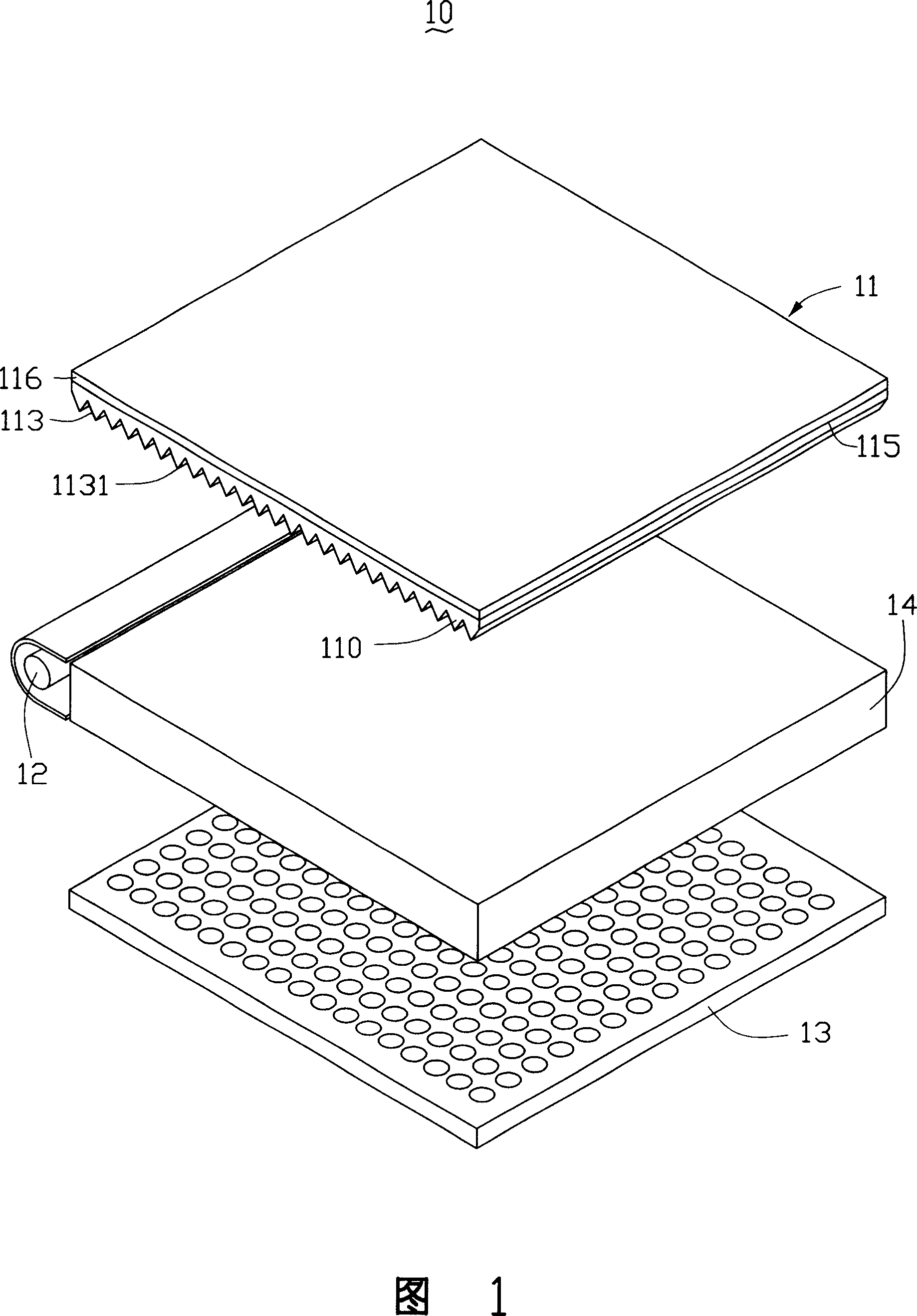
【Technical field】 [0001] The invention relates to a prism sheet applied to a liquid crystal display device and a backlight module using the prism sheet. 【Background technique】 [0002] In recent years, liquid crystal displays have been widely used due to their lightness, thinness, small size and low power consumption. Since the liquid crystal display panel itself does not have light-emitting characteristics, a backlight module is required to provide a backlight for it to realize the display function of the liquid crystal display panel. [0003] Please refer to FIG. 1 , which is an exploded view of a prior art backlight module. The backlight module 10 includes a prism sheet 11 , a light source 12 , a reflection plate 13 and a light guide plate 14 . The prism sheet 11 includes a base body 110, one surface of the base body 110 is a light incident surface 113 for receiving light beams, and the light incident surface 113 is provided with a plurality of V-shaped grooves 1131 par...

Claims


Application Information

Patent Timeline
Patent Type & Authority Applications(China)
IPC IPC(8): G02B5/04G02F1/1335
CPCG02B5/045G02B6/0053
Inventor 岳国汉
Owner HONG FU JIN PRECISION IND (SHENZHEN) CO LTD
Learn More