Attachment/detachment mechanism for compact antenna
A technology of a small antenna and a loading and unloading mechanism, which is applied in the directions of the antenna, the antenna support/installation device, and the structural connection of the antenna grounding switch, etc., can solve the problems such as the destruction of the antenna part 12
- Summary
- Abstract
- Description
- Claims
- Application Information
AI Technical Summary
Problems solved by technology
Method used
Image

Examples
Embodiment 1
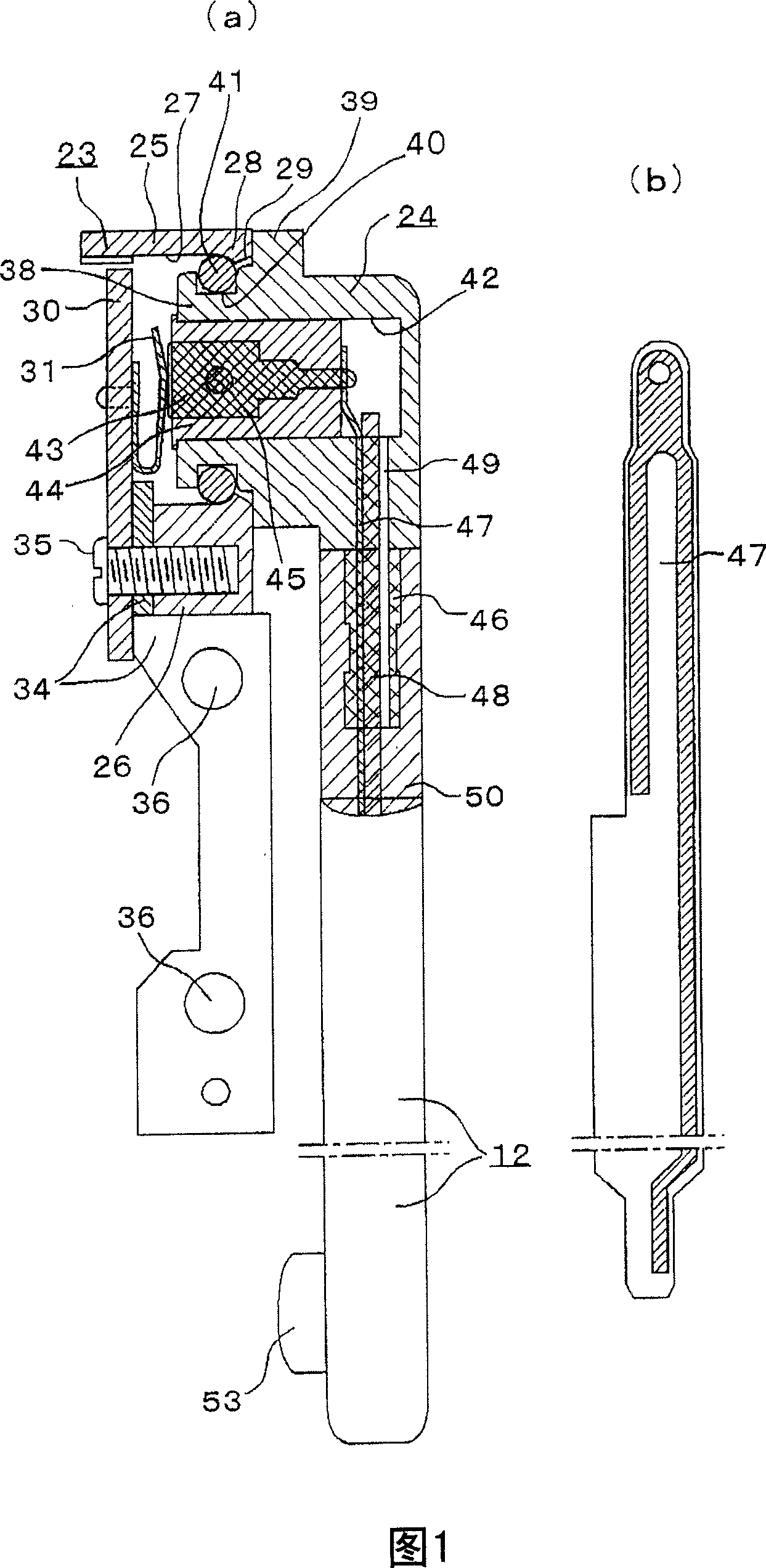
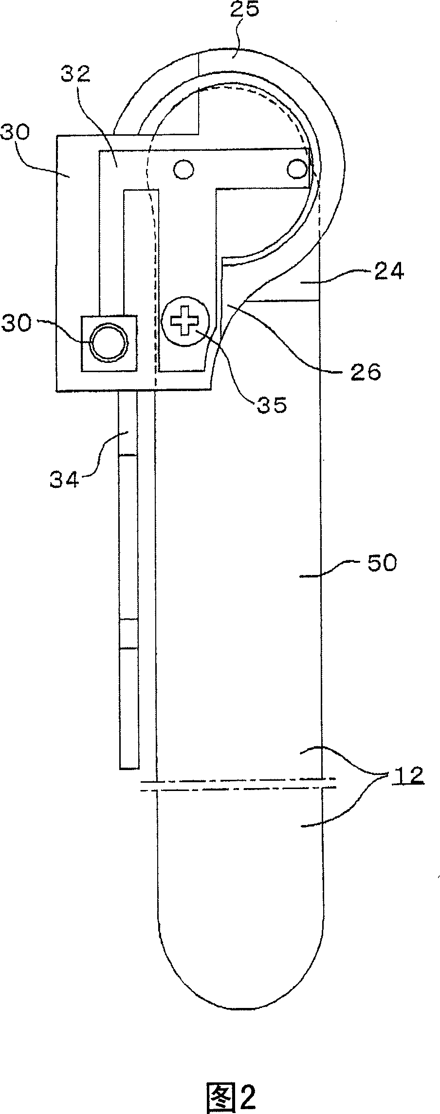
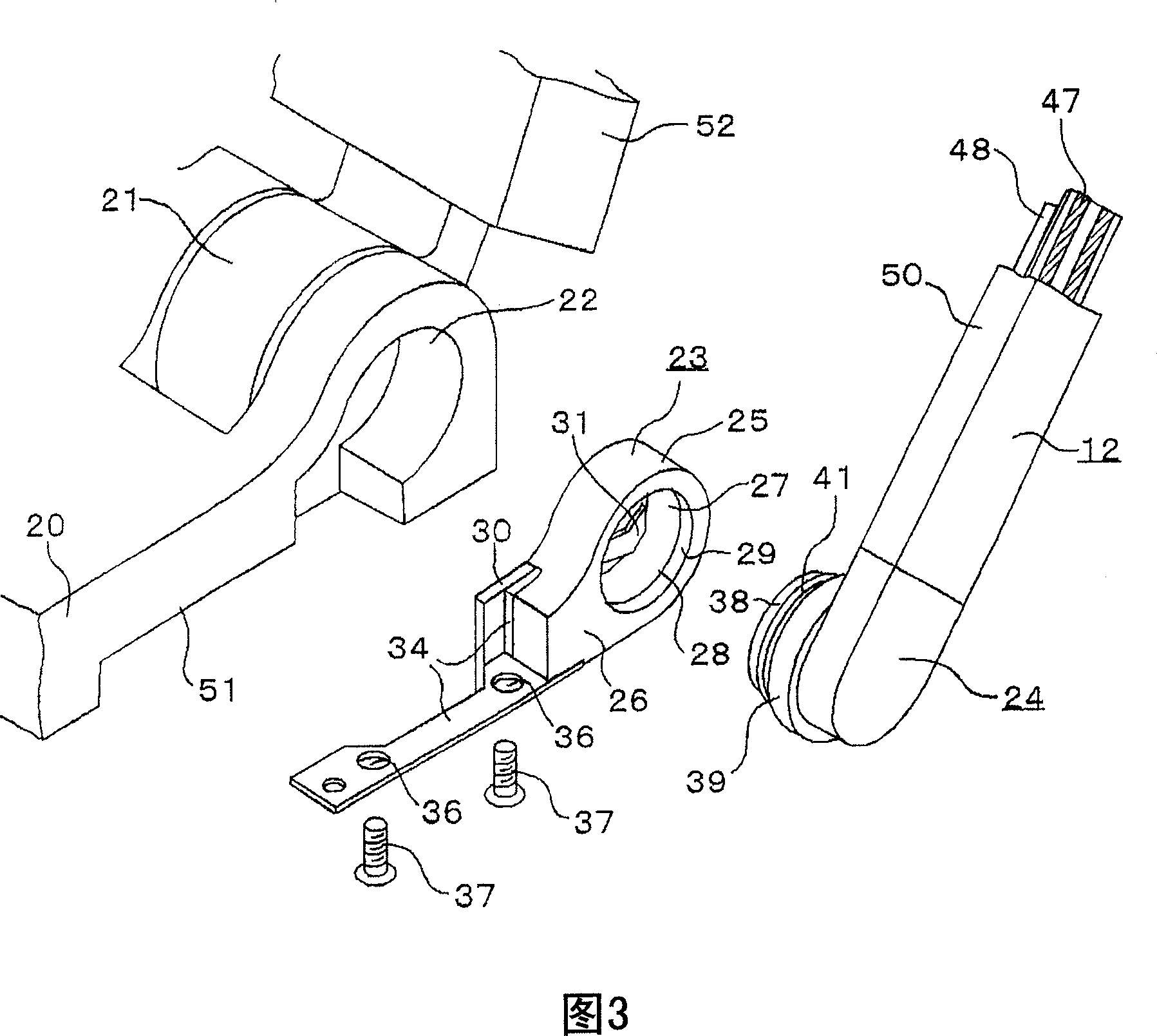
[0030] Embodiment 1 of the attachment and detachment mechanism of the small antenna of the present invention will be described based on FIGS. 1 to 3 .
[0031]In FIG. 3 , a display 52 is openably and closably attached to an electronic device body 20 such as a notebook computer via a hinge portion 21 . An antenna mounting portion 22 is provided at a side end portion of the hinge portion 21 to fit and mount an antenna holder 23 to be described later.
[0032] The antenna holder 23 is made of an insulator such as plastic, and includes a fitting tube 25 having a diameter of approximately 11 mm and openings at both ends, and a base 26 extending from the fitting tube 25 to one side. In one opening of the fitting cylinder 25, a locking protrusion 28 is formed on an inner peripheral portion near the opening end so as to detachably fit a later-described L-shaped connector 24 for rotation. The opening end side of the locking protrusion 28 serves as a tapered portion 29 for guiding when...
Embodiment 2
[0045] In the above-mentioned first embodiment, the O-ring 41 is provided on the rotation L-shaped connector 24 on the antenna part 12 side, and the locking protrusion 28 is provided on the fitting cylinder part 25 on the antenna holder 23 side, and vice versa. As shown in FIG. 4 , a locking protrusion 28 may be provided on the rotation L-shaped connector 24 on the antenna part 12 side, and an O-ring 41 may be provided on the fitting cylinder part 25 on the antenna holder 23 side. In this case, use the force of the contact spring 31 to press the engaging convex portion 28 on the side of the fitting cylinder portion 38 into the side surface of the O-ring 41, and restrict the movement of the antenna portion 12 due to its own weight or a relatively small force. to become a stable bonded state.
Embodiment 3
[0047] In the above-mentioned embodiments 1 and 2, the O-ring is made into a ring shape. As shown in FIG. In this case, the wall portions on both sides of the fitting groove 40 are slightly curved inwardly above the center of the ball 54 so that the ball 54 does not escape from the fitting groove 40 .
PUM
 Abstract
Description
Claims
Application Information
 - R&D
- Intellectual Property
- Life Sciences
- Materials
- Tech Scout
- Unparalleled Data Quality
- Higher Quality Content
- 60% Fewer Hallucinations
Browse by: Latest US Patents, China's latest patents, Technical Efficacy Thesaurus, Application Domain, Technology Topic, Popular Technical Reports.
© 2025 PatSnap. All rights reserved.Legal|Privacy policy|Modern Slavery Act Transparency Statement|Sitemap|About US| Contact US: help@patsnap.com