System for accessing, monitoring and exchanging network video

A network video monitoring and switching system technology, applied in the field of network access and switching systems, can solve the problems of not being able to directly interconnect and intercommunicate, not considering commercial services, and not being able to provide access solutions, etc.

Inactive Publication Date: 2007-09-05
南京艾迪恩斯数字技术有限公司 +1
View PDF0 Cites 33 Cited by
  • Summary
  • Abstract
  • Description
  • Claims
  • Application Information

AI Technical Summary

Problems solved by technology

However, the current IP network multicast service model did not consider clear commercial services when it was initially defined, and the multicast management and multicast address allocation of each switching node and access node in the network cannot be well unified. Management and control to meet commercial needs, that is, the network video surveillance system in the fourth stage cannot fully utilize the multicast characteristics of surveillance video streams for system multicast switching, resulting in increased IP bearer network bandwidth and unnecessary waste of node equipment. The cost of network construction and use, especially cannot meet the video service requirements of multi-users with high image quality; in the fourth stage, the network video surveillance system cannot directly and comprehensively access video equipment because the access equipment is a general network equipment. The video surveillance system built in the first stage cannot provide a good access solution in terms of network transformation and other aspects; the embedded video server used in the fourth stage network video surveillance system is currently not flexible enough in structure and has a single access form, especially in Insufficient attention has been paid to the integration with the network access layer. Similar network access problems exist in the digital video matrix used to connect to the video matrix wall. At present, there is no unified standard for video surveillance. The video coding standards and frame formats of video streams adopted are different, and basically cannot be directly interconnected and intercommunicated with each other. The network video surveillance system in the fourth stage does not have a good solution for video interconnection and intercommunication within the system and between systems.

Method used


Image

  • System for accessing, monitoring and exchanging network video
  • System for accessing, monitoring and exchanging network video
  • System for accessing, monitoring and exchanging network video

Examples


Embodiment Construction

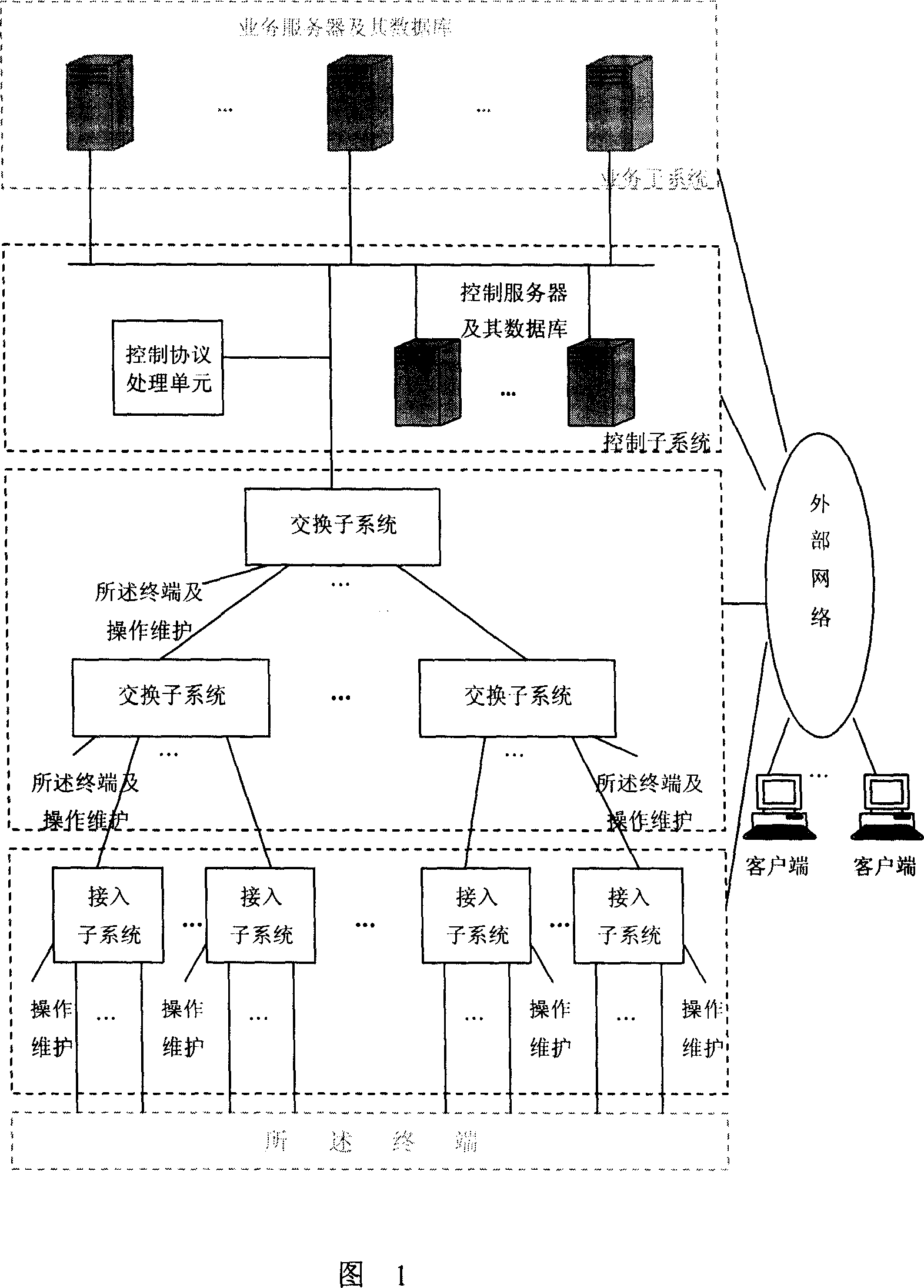
[0074] Fig. 1 is a physical structure diagram of the network video surveillance access switching system described in one of the objects of the present invention. Its physical structure is that the system includes an access subsystem, a switch subsystem and a control subsystem, and each subsystem is a physical entity that may be located in different physical locations. The connection between the access subsystem and the switching subsystem and between the switching subsystem and the switching subsystem is through Ethernet, and its transmission can be direct connection with cables such as optical fibers, or SDH transmission network, etc. The control subsystem, the access subsystem, and the switching subsystem are connected through Ethernet or IP. When connecting through Ethernet, it is directly carried by the Ethernet switching network composed of switching subsystems inside the system. When connecting through IP, Its bearer can be the Ethernet switching network inside the syste...


PUM


Abstract

The invention is used in the interface boards for connecting multi terminals to external network and the service single board for interconnecting the function board of video gateway. In the invention, by connecting the Ethernet interface to system Ethernet exchange network, under the control of control subnet, said system Ethernet exchange system can realizes Ethernet multicast and IP multicast. The network video monitoring access system equipped with said system can be used to establish the network video monitoring system required by all application fields such as enterprise network, metropolitan area network, communication network, IPTV and internet to provide video service.

Description

technical field [0001] The invention generally relates to a video monitoring system, and particularly relates to a network access and switching system of a networked video monitoring system. Background technique [0002] my country's video surveillance technology has experienced the first stage of analog video surveillance in the early stage, the second stage of digital video surveillance based on industrial computer plug-in cards in the mid-1990s, and the third stage of network video surveillance based on video servers in the late 1990s. The common characteristics of these three stages are that they mainly focus on terminal equipment, and do not pay enough attention to network construction, especially network access and exchange. Network video surveillance system. [0003] At present, there is a fourth-stage network video monitoring system constructed by using Intranet / Internet and other networks as switching networks and accessing embedded video servers through network ac...

Claims


Application Information

Patent Timeline
Patent Type & Authority Applications(China)
IPC IPC(8): H04L12/28H04N7/18
Inventor 华漪王宁
Owner 南京艾迪恩斯数字技术有限公司
Why Eureka
Try Eureka