Mold clamping force detection method

A detection method and a clamping force technology, applied in the field of clamping force detection for detection of clamping force, can solve the problem that the detection of clamping force does not require much accuracy, etc.

Inactive Publication Date: 2007-09-05
SUMITOMO HEAVY IND LTD
View PDF1 Cites 8 Cited by
  • Summary
  • Abstract
  • Description
  • Claims
  • Application Information

AI Technical Summary

Problems solved by technology

In the conventional deformation detection device used to detect the mold clamping force of the injection molding machine, since the detection accuracy of the mold clamping force is not very high, there is no implementation for the detection error of the mold clamping force caused by the deviation of the output voltage. Countermeasures

Method used


Image

  • Mold clamping force detection method
  • Mold clamping force detection method
  • Mold clamping force detection method

Examples


Embodiment Construction

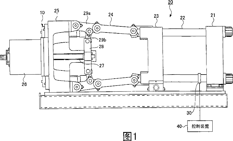
[0044] Hereinafter, a mold clamping device of an injection molding machine as a device to which the deformation detection device of the present invention can be used will be briefly described with reference to FIG. 1 .

[0045] Fig. 1 is a side view of a mold clamping device of an injection molding machine equipped with a deformation detection device according to the present invention. The mold clamping device shown in FIG. 1 has a mold thickness adjusting device 10 and a mold clamping mechanism 20 . The mold clamping mechanism 20 is a toggle-type mold clamping mechanism, and has a fixed plate 21, a tie rod 22, a movable plate 23, an arm 24, a toggle support portion 25, a mold clamping servo motor 26, a ball screw 27, and a crosshead. 28.

[0046] A fixed die (not shown) is attached to the fixed plate 21 , and a movable die (not shown) is attached to the movable plate 23 . By moving the movable plate 23 along the tie rods 22, the movable mold is moved relative to the fixed m...


PUM


Abstract

A mold clamp force detection method for detecting a mold clamping force based on an output from a strain detector (30) installed on the mold clamping device of a molding machine. A first output value output from the strain detector (30) is detected when the mold clamping device is in a fully opened state. While the mold clamping force is generated by the mold clamping device, a second output value output from the strain detector (30) is corrected based on the first output value. The mold clamping force is provided based on the corrected second output value. The output from the strain detector (30) is converted into a digital value and corrected or, by using a strain gauge (50), a reference voltage fed to the comparison amplifier of the strain gauge is changed based on the first output value.

Description

technical field [0001] The invention relates to a mold clamping force detection method, in particular to a mold clamping force detection method using a strain gauge for measuring the deformation of a pull rod of a mold clamping device of a forming machine to detect the mold clamping force. Background technique [0002] For example, as a mechanism for detecting clamping force in a mold of an injection molding machine, a method of measuring deformation (elongation) of a tie rod of a mold clamping device and converting the measured deformation into a mold clamping force has been proposed. A tensile stress proportional to the clamping force occurs on the tie rod. By detecting the deformation (elongation) of the tie rod due to the tensile stress, the mold clamping force actually applied to the mold can be obtained. [0003] As a mechanism for detecting deformation of a rod-shaped member such as a tie rod, a strain gauge is generally used (for example, refer to Patent Document 1)...

Claims


Application Information

Patent Timeline
Patent Type & Authority Applications(China)
IPC IPC(8): B29C45/66B22D17/32B22D17/26B29C45/76
CPCB22D17/26B22D17/32B29C45/7653B29C2945/76234B29C2945/76481B29C45/64B29C45/76
Inventor 伊藤晃
Owner SUMITOMO HEAVY IND LTD
Why Eureka
Try Eureka