Input isolation of a transimpedance amplifier in optical receivers

a transimpedance amplifier and optical receiver technology, applied in the field of optical receivers, can solve the problems of deteriorating affecting the frequency response of the switch, and affecting the performance of the optical receiver

Active Publication Date: 2013-11-12
ORACLE INT CORP
View PDF3 Cites 4 Cited by
  • Summary
  • Abstract
  • Description
  • Claims
  • Application Information

AI Technical Summary

Benefits of technology

[0023]Another embodiment provides a method for calibrating and biasing the optical receiver. In this method, during the normal mode the input of the TIA is electrically coupled to the OE converter. Moreover, during the calibration mode, the input of the TIA is electrically isolated from the OE converter while maintaining the feedback path from the output to the input of the TIA's amplifier, thereby ensuring proper bias of the TIA during calibration. Note that the frequency response of the TIA during the normal mode is substantially unchanged over an operating bandwidth of the TIA by the capability to electrically isolate the input of the TIA from the OE converter during the calibration mode.

Problems solved by technology

However, this isolation technique has several drawbacks.
Notably, the performance of the optical receiver may be degraded by the added parasitic resistance and capacitance associated with the introduction of such a switch.
In this range, the additional series resistance associated with the introduction of an isolation switch between the PD and the TIA (as shown in FIGS. 2A and 2B) may significantly deteriorate the performance of the optical receiver.
If Rswitch is large compared to Rsmall, Rswitch can significantly degrade the frequency response.
But even at this minimum value, the degradation in the frequency response of the optical receiver may not be acceptable.
These requirements may increase the overhead with a commensurate degradation in the effective data rate.
However, this technique does not provide true isolation, and may also require that DC-balanced data be communicated to the optical receiver by an optical transmitter.
In addition, the averaging may introduce additional problems, including: residual ripple (i.e., the averaging may not be perfect); the averaging circuit may contribute undesirable parasitics along the signal path; and the averaging may behave poorly when the input signal is saturated.

Method used


Image

  • Input isolation of a transimpedance amplifier in optical receivers
  • Input isolation of a transimpedance amplifier in optical receivers
  • Input isolation of a transimpedance amplifier in optical receivers

Examples


Embodiment Construction

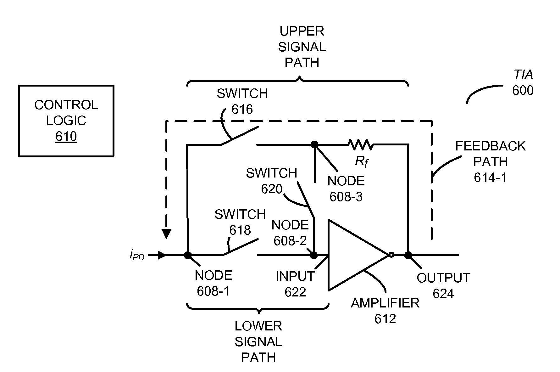
[0040]Embodiments of an optical receiver, a system that includes the optical receiver, and a technique for calibrating and biasing the optical receiver are described. This optical receiver has two operating modes: a calibration mode and a normal mode. During the normal mode, switches are used to electrically couple an input of a transimpedance amplifier (TIA) to an optical-to-electrical (OE) converter that receives an optical signal and provides a corresponding analog electrical signal. Moreover, during the calibration mode, the switches are used to electrically isolate the input of the TIA from the OE converter while maintaining a feedback path from an output of the TIA to the input of the TIA, thereby ensuring proper bias of the TIA during calibration. Furthermore, a frequency response of the TIA during the normal mode is substantially unchanged over an operating bandwidth of the TIA by the capability to electrically isolate the input of the TIA from the OE converter during the ca...


PUM


Abstract

An optical receiver is described. This optical receiver has two operating modes: a calibration mode and a normal mode. During the normal mode, switches are used to electrically couple an input of a transimpedance amplifier (TIA) to an optical-to-electrical (OE) converter that receives an optical signal and provides a corresponding analog electrical signal. Moreover, during the calibration mode, the switches are used to electrically isolate the input of the TIA from the OE converter while maintaining a feedback path from an output of the TIA to the input of the TIA, thereby ensuring proper bias of the TIA during calibration. Furthermore, a frequency response of the TIA during the normal mode is substantially unchanged over an operating bandwidth of the TIA by the capability to electrically isolate the input of the TIA from the OE converter during the calibration mode.

Description

GOVERNMENT LICENSE RIGHTS[0001]The United States Government has a paid-up license in this invention and the right in limited circumstances to require the patent owner to license others on reasonable terms as provided for by the terms of Agreement No. HR0011-08-9-0001 awarded by the Defense Advanced Research Projects Administration.BACKGROUND[0002]1. Field[0003]The present disclosure relates to optical receivers. More specifically, the present disclosure relates to optical receivers in which inputs to a transimpedance amplifier can be isolated during a calibration mode.[0004]2. Related Art[0005]As illustrated in FIG. 1, a typical existing optical receiver includes an optical-to-electrical (OE) converter that receives an optical signal, and which generates a corresponding electrical signal. Then, an amplification chain converts the electrical signal into digital voltage levels.[0006]For example, a common OE converter is a photodetector (PD). It converts an incoming optical signal to a...

Claims


Application Information

Patent Timeline
Patent Type & Authority Patents(United States)
IPC IPC(8): H04B10/60H04B10/69
CPCH04B10/693H04B10/695
Inventor LIU, FRANKIE Y.PATIL, DINESH D.
Owner ORACLE INT CORP
Why Eureka
Try Eureka