
Wide-spectrum-band diffraction optical imaging system

A diffractive optics and imaging system technology, applied in the field of wide-spectrum diffractive optics imaging systems, can solve problems such as insufficient elimination of diffractive optical elements, inability to meet imaging requirements, and difficulty in implementation, so as to reduce the difficulty of chromatic aberration correction and achieve miniaturization , the effect of reducing hardware complexity

Active Publication Date: 2015-10-28
BEIJING RES INST OF SPATIAL MECHANICAL & ELECTRICAL TECH
View PDF3 Cites 4 Cited by
  • Summary
  • Abstract
  • Description
  • Claims
  • Application Information

AI Technical Summary

Problems solved by technology

There are two problems in the chromatic aberration correction of the diffractive optical system. One is that the traditional lens is not enough to eliminate the huge chromatic aberration produced by the diffractive optical element; the other is to use the classic Schupmann chromatic aberration correction method, that is, to use another diffractive optical element with an opposite phase to correct the system chromatic aberration. The two diffractive optical elements in the system need to be strictly aligned. Although this method can achieve wide-spectrum imaging, it has defects such as too long a system and strict tolerances. It is difficult to realize and its application is limited.
At present, foreign countries based on the Schupmann method have achieved a spectral bandwidth of 50nm, which still cannot meet the imaging requirements

Method used


Image

  • Wide-spectrum-band diffraction optical imaging system
  • Wide-spectrum-band diffraction optical imaging system
  • Wide-spectrum-band diffraction optical imaging system

Examples


Embodiment Construction

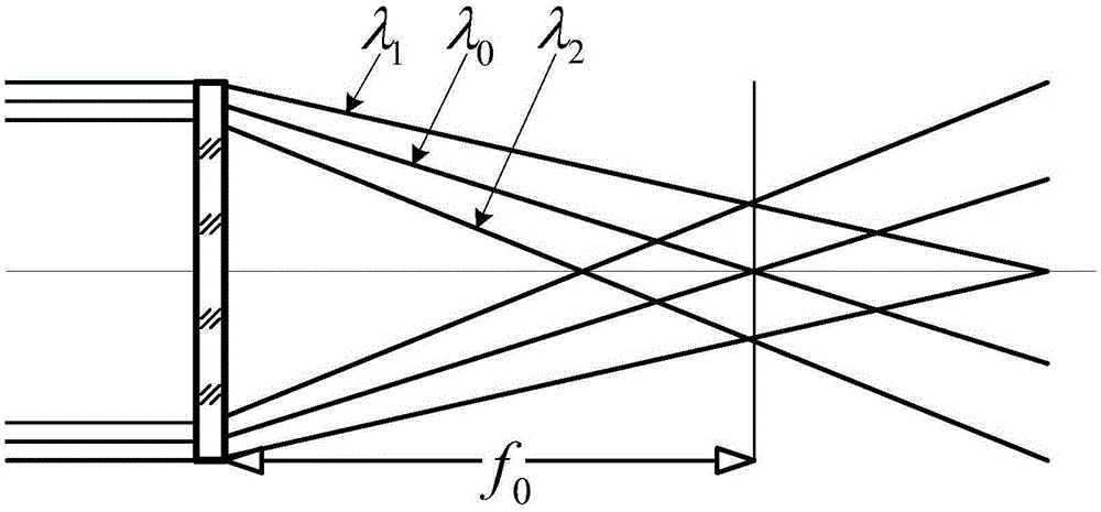
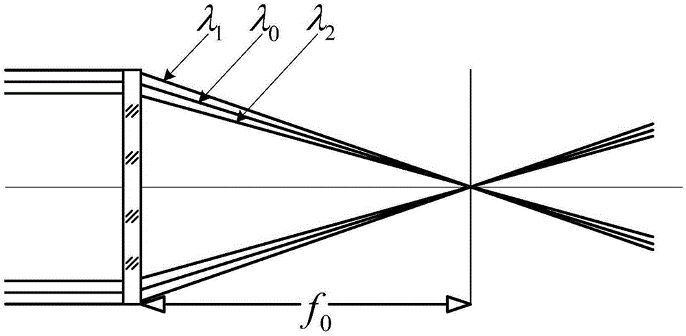
[0024] The present invention proposes a wide-spectrum diffractive optical imaging system, such as figure 1 As shown, it includes: an optical module, a detector module and an image restoration module; the optical module includes a harmonic diffractive optical element and a wavefront encoding element, and the wavefront encoding element is placed between the harmonic diffractive optical element and the detector module; Convergent imaging of optical elements, the wavefront encoding element performs aberration modulation on the converging light; the detector module receives the modulated light and performs photoelectric conversion to obtain the modulated image; the image restoration module decodes the modulated image output by the detector module Adjustment can eliminate aberrations and obtain wide-spectrum clear images.

[0025] The harmonic diffractive optical element is the primary mirror of the wide-spectrum diffractive optical imaging system, and the phase modulation function ...


PUM

PropertyMeasurementUnit
Spectral bandwidthaaaaaaaaaa

Abstract

Provided is a wide-spectrum-band diffraction optical imaging system. The wide-spectrum-band diffraction optical imaging system comprises an optical module, a detector module, and an image restoration module, the optical module comprises a harmonic diffractive optical element and a wave-front coding element, lights are collected to images via the harmonic diffractive optical element, aberration modulation of the collected lights is performed via the wave-front coding element, the detector module receives the modulated lights for photoelectric conversion and obtains the images, the image restoration module processes the images outputted by the detector module, removes the modulation effect of the wave-front coding element on the collected lights, and eliminates the aberration with the combination of modulation information of the collected lights by the wave-front coding element, and the images are obtained. According to the wide-spectrum-band diffraction optical imaging system, the harmonic diffractive optical element is regarded as the main lens of the optical system, the characteristic of achromatism of the harmonic diffractive optical element and the characteristic of aberration correction of the wave-front coding technology are employed, the spectrum bandwidth is wide, the complexity and tolerance constraint of the system are reduced, and the diffraction optical imaging system is more easily realized.

Description

technical field [0001] The invention relates to an optical imaging system, in particular to a wide-spectrum diffractive optical imaging system. Background technique [0002] Diffractive optical elements are usually used as achromatic and athermal elements in traditional optical systems due to their large dispersion characteristics. Since the diffractive optical element has the characteristics of a planar shape and a thin film as the substrate, it is very easy to realize a super-large-aperture optical system by using it as the primary mirror of the optical system, and has important application prospects in the field of super-large-aperture optical imaging. [0003] Diffractive optical imaging technology uses diffractive optical elements instead of traditional lenses or mirrors as the main mirror of the optical imaging system. The diffractive optical element can be processed on a flat substrate, which reduces the weight of the system to a certain extent, and the dispersion ch...

Claims


Application Information

Patent Timeline
IPC IPC(8): G02B27/42
CPCG02B27/4205G02B27/4211
Inventor 焦建超张秉隆王保华张月王超金建高阮宁娟苏云郭崇岭吴立民
Owner BEIJING RES INST OF SPATIAL MECHANICAL & ELECTRICAL TECH
Learn More