
Panoramic imaging lens free of central blind area

A panoramic imaging lens, no blind spot technology, applied in the field of panoramic imaging lens, can solve the problems of reduced security, affecting the integrity of imaging, aesthetics, etc., and achieves the effects of low energy loss, simple structure, and low chromatic aberration

Inactive Publication Date: 2016-11-30
上海臻恒光电系统有限公司
View PDF4 Cites 2 Cited by
  • Summary
  • Abstract
  • Description
  • Claims
  • Application Information

AI Technical Summary

Problems solved by technology

This central blind spot not only affects the integrity and beauty of imaging, but also greatly reduces the safety in practical application fields such as security and surveillance.

Method used


Image

  • Panoramic imaging lens free of central blind area
  • Panoramic imaging lens free of central blind area
  • Panoramic imaging lens free of central blind area

Examples


Embodiment Construction

[0039] Hereinafter, the present invention will be described in detail with reference to the drawings and embodiments. The following examples do not limit the invention. Without departing from the spirit and scope of the inventive concept, changes and advantages that can be imagined by those skilled in the art are all included in the present invention.

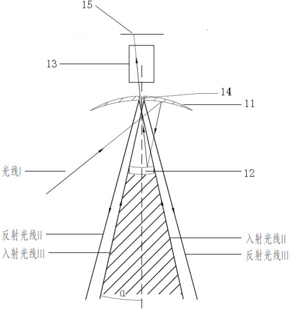
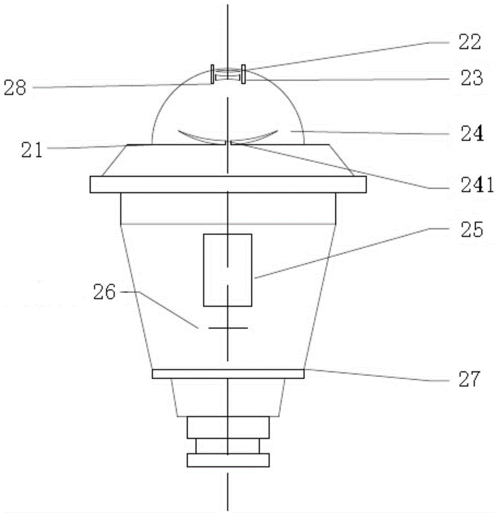
[0040] figure 2 It is a structural schematic diagram of a panoramic imaging lens without a central blind spot according to an embodiment of the present invention. image 3 It is an exploded schematic diagram of a panoramic imaging lens without a central blind spot according to an embodiment of the present invention. Figure 5 It is a schematic diagram of optical path constraints in the central field of view of a panoramic imaging lens without a central blind zone according to an embodiment of the present invention.

[0041] Such as figure 2 , 3 As shown, the panoramic imaging lens without a central blind spot according t...


PUM


Abstract

The invention provides a panoramic imaging lens free of a central blind area. The panoramic imaging lens comprises, from the side of an object along the direction of optical axis, an adjusting lens (22), a semi-transparent semi-reflective lens (23) and a concave reflector (24). A round hole (241) is formed in the center of the concave reflector (24). The optical axis serves a rotation symmetry axis for the adjusting lens (22), the semi-transparent semi-reflective lens (23) and the concave reflector (24). The adjusting lens (22) is used for converging light rays emitted by objects in an original central blind area; the concave reflector (24) is used for reflecting light rays emitted by objects outside the original central blind area to the semi-transparent semi-reflective lens (23); the semi-transparent semi-reflective lens (23) is used for transmitting incident rays from the adjusting lens (22), enabling the incident rays to pass through the round hole (241) of the concave reflector (24), reflecting reflection rays from the concave reflector (24), and enabling the reflection rays to pass through the round hole (241) of the concave reflector (24), so that imaging of the light rays from the adjusting lens (22) and the light rays from the concave reflector (24) is achieved on a focal plane.

Description

technical field [0001] The invention relates to the technical field of imaging lenses, in particular to a panoramic imaging lens without a central blind spot. Background technique [0002] The optical field of view of the panoramic ring optical lens can be considered to be composed of optical fields in two directions. In the Cartesian polar coordinate system, the optical field of view in one direction is located in the XOY plane, that is, the field of view in the azimuth direction is 360°; the size of the optical field in the other direction is the difference in pitch angle of the system. Such an annular optical lens can image a scene in a 360° annular field of view in the XOY plane to achieve a special panoramic imaging effect. [0003] At present, there are many forms of panoramic ring lenses, mainly including refraction and reflection. The reflective panoramic ring lens includes two reflective panoramic lenses. figure 1 It is a schematic diagram showing the main struct...

Claims


Application Information

Patent Timeline
Patent Type & Authority Applications(China)
IPC IPC(8): G02B13/06G02B13/00
Inventor 徐建华周中能潘海峰方中华李磊赵力涛
Owner 上海臻恒光电系统有限公司
Learn More