Centrifugal shaping tool

A centrifugal molding and tooling technology, which is applied in the manufacture of tools, ceramic molding machines, ceramic molding cores, etc., can solve the problems of easy interference phenomenon, inconvenient operation, and complex structure of automatic molding centrifugal devices.

Inactive Publication Date: 2007-09-12
湖南邱则有专利战略策划有限公司
View PDF1 Cites 1 Cited by
  • Summary
  • Abstract
  • Description
  • Claims
  • Application Information

AI Technical Summary

Problems solved by technology

[0005] However, the structure of this thin-walled cement pipe automatic forming centrifugal device is still relatively complicated. When installing and disassembling the forming mold in the rotating cylinder, it is

Method used


Image

  • Centrifugal shaping tool
  • Centrifugal shaping tool
  • Centrifugal shaping tool

Examples


Embodiment Construction

[0107] The present invention will be further described below in conjunction with the accompanying drawings and embodiments.

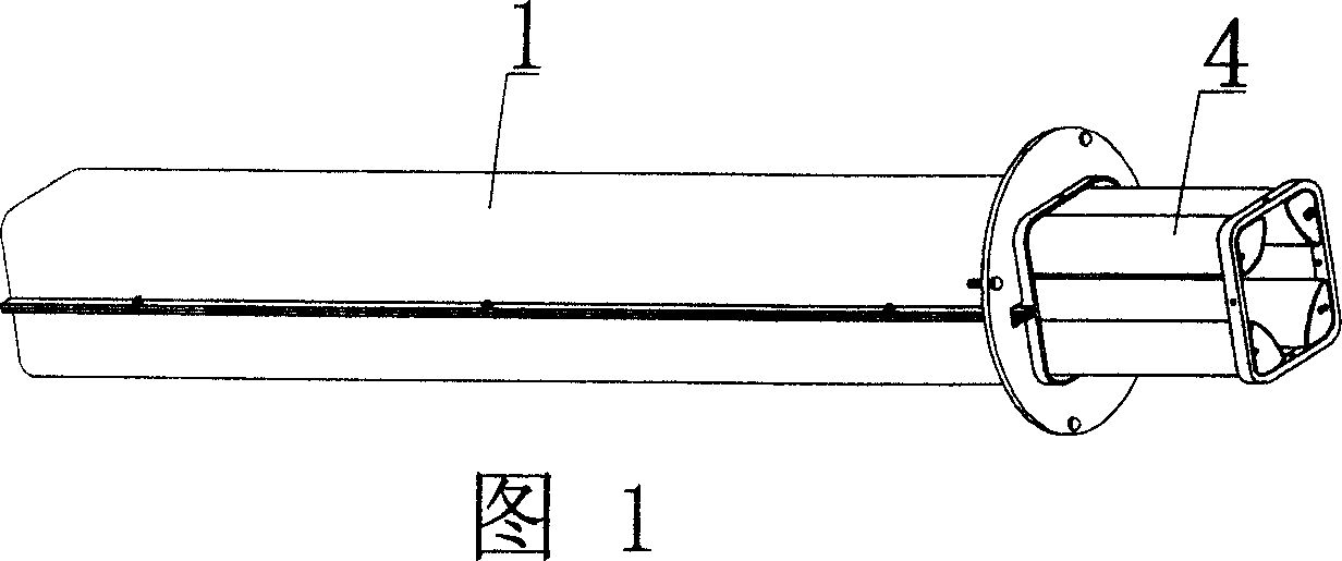
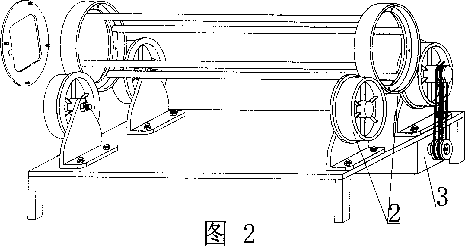
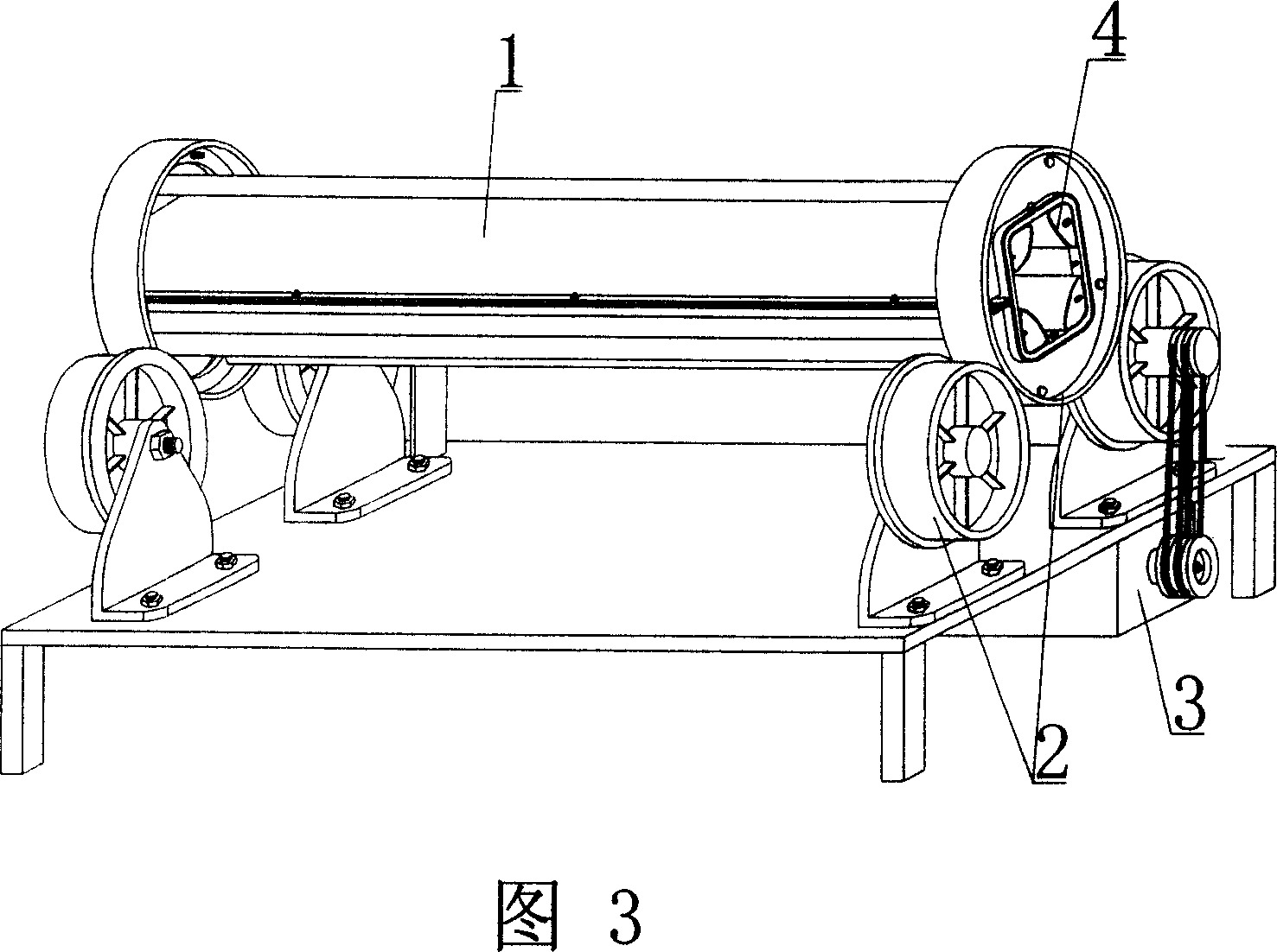
[0108] As shown in the accompanying drawings, the present invention includes a ring-shaped mold 1, a mold support 2, and a centrifugal drive member 3, and is characterized in that the ring-shaped mold 1 has at least one core mold 4 that limits the internal shape of the product. In each accompanying drawing, 1 is an annular tubular mold, 2 is a mold support, 3 is a centrifugal drive member, and 4 is a mandrel. In the following accompanying drawings, those with the same number have the same description. As shown in FIG. 3 , there are four core molds 4 that limit the internal shape of the product in the annular tubular mold 1 . FIG. 1 is a process diagram of the core mold 4 extending into the annular tubular mold 1 ; FIG. 2 is a schematic diagram of the mold support 2 and the centrifugal driving member 3 .

[0109] The present invention is also characteri...


PUM


Abstract

The centrifugal forming tool includes one tubular mold, one mold supporting frame and one centrifugal driving part; and features that the tubular mold has at least one core mold to limit the inside shape of the product. The tubular mold with core mold may be used in producing thin wall cement members of different cross section shapes. The forming tool of the present invention has simple structure, easy manufacture, high strength, low cost and other features, and is suitable for producing thin wall pipe or box, especially thin wall pipe or box with opened mouth.

Description

(1) Technical field [0001] The invention relates to a centrifugal forming tool. (2) Background technology [0002] At present, the production of thin-walled cement pipes for domestic cast-in-place concrete hollow floors is usually manually operated, which has high labor intensity, low production efficiency, uneven wall thickness, poor product quality, and waste of production materials. In order to solve the current The technical problems existing in actual production, the patent No. ZL03211400.1, titled "a kind of centrifugal device for automatic forming of thin-walled cement pipes" solved the above problems well. This thin-walled cement pipe automatic forming centrifugal device includes a support base, a support roller, a pressure plate, a clamping bolt, a pressure rod bracket, a pin shaft, a pressure rod, a forming mold, a rotating cylinder, a coupling, a motor, and a main shaft. One end of the rotating cylinder is provided with a central main shaft, which is connected to...

Claims


Application Information

Patent Timeline
IPC IPC(8): B28B21/30B28B21/80B28B21/82B28B21/88
Inventor 邱则有
Owner 湖南邱则有专利战略策划有限公司
Why Eureka
Try Eureka