Method and apparatus for realizing quantization in coding/decoding process

An encoding/decoding and encoding unit technology, applied in the field of quantization, can solve problems such as affecting image encoding efficiency and transmission performance, increasing user processing complexity, etc., to achieve the effects of ensuring subjective quality, improving image quality, and saving encoding efficiency

Inactive Publication Date: 2007-09-19
HUAWEI TECH CO LTD +1
View PDF0 Cites 39 Cited by
  • Summary
  • Abstract
  • Description
  • Claims
  • Application Information

AI Technical Summary

Problems solved by technology

[0060] It can be seen from the specific quantization implementation methods of the above-mentioned various encoding methods that in the actual application process, the implementation solutions provided by the prior art, on the one hand, need to adjust the corresponding frequency components of each frequency component in the entire quantization

Method used


Image

  • Method and apparatus for realizing quantization in coding/decoding process
  • Method and apparatus for realizing quantization in coding/decoding process
  • Method and apparatus for realizing quantization in coding/decoding process

Examples


Embodiment 1

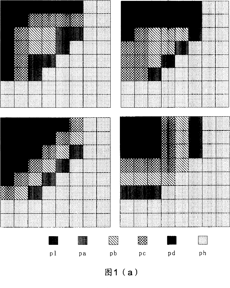
[0134] Figure 1(a) shows an example of quantization parameter model of 8×8 matrix, 6 frequency band parameters (q_para[i], i=1...6), and 4 frequency band distribution parameters (q_mode=0...3).

[0135] That is, in Figure 1(a), 6 parameters (pl, pa, pb, pc, pd, ph) are assigned to represent 6 frequency bands, and in each 8×8 matrix, the parameters (pl, pa, pb, pc , pd, ph) have different distribution positions in the matrix, which corresponds to a distribution model, which is represented by the frequency band distribution parameter q_mode.

[0136] For example, there are four distribution models listed in Figure 1(a), that is, the frequency band distribution parameter q_mode can take values ​​of 0, 1, 2, and 3.

[0137] That is, the corresponding quantization model is expressed as:

[0138] Q x,y [i]=(q_mode, q_para[i]) i=1...6, x,y=0...7;

[0139] or,

[0140] Q x,y [i]=(q_para[i], q_mode) i=1...6, x, y=0...7.

[0141] Wherein, WQ is a weighted quantization parameter ma...

Embodiment 2

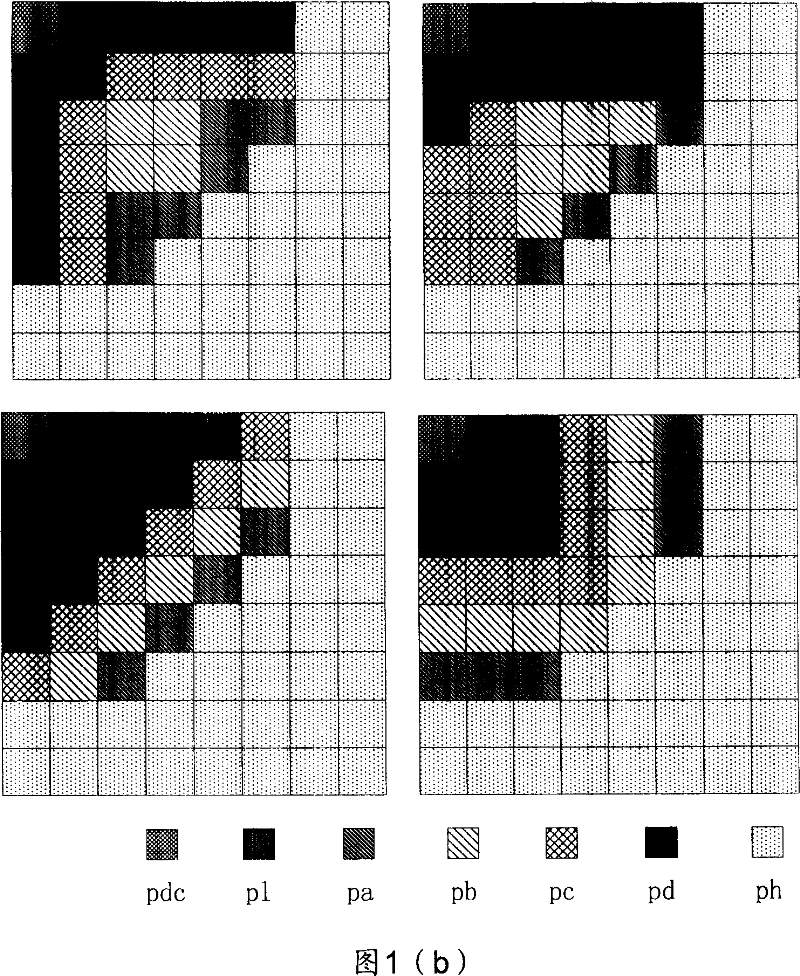
[0143] As shown in Fig. 1(b), an example of quantization parameter model of 8×8 matrix, 7 frequency band parameters (q_para[i], i=1...7), and 4 frequency band distribution parameters is given.

[0144] That is, in Figure 1(b), an example of a distribution structure of 7 parameters is given, where the 7 parameters (pdc, pl, pa, pb, pc, pd, ph) represent 7 frequency bands respectively; When , the corresponding parameter quantization model can be expressed as:

[0145] Q x,y [i]=(q_mode, q_para[i])i=1...7, x,y=0...7;

[0146] or,

[0147] Q x,y [i]=(q_para[i], q_mode) i=1...7, x, y=0...7.

[0148] Therefore, a parametric quantization model with n band parameters can be expressed as:

[0149] Q x,y [i]=(q_mode, q_para[i]), i=1...n, x=0...M-1, y=0...N-1 (2)

[0150] or,

[0151] Q x,y [i]=(q_para[i], q_mode) i=1...n, x=0...M-1, y=0...N-1 (3)

[0152] Wherein, n

Embodiment 3

[0154] As shown in Figure 1(a), an 8×8 matrix, 4 groups of 6 frequency band parameters (q_para[i], i=1...6), and a quantization parameter model of 4 frequency band distribution parameters (q_mode=0...3) example.

[0155] Among them, q_para[i], i=1...n is a group of frequency band parameters, each given a set of q_para[i] values, i=1...n, that is, a parameter set is determined, and the parameter set index is recorded as wq_param k ;

[0156] Taking the 6-band parameter model shown in Figure 1(a) as an example, for different frequency-band parameters (p1, pa, pb, pc, pd, ph) values, parameter sets of different frequency-band parameters can be obtained, for example:

[0157] The first group of frequency band parameters: wq_param 1=(pl 1 , pa 1 , pb 1 , pc 1 , pd 1 ,ph 1 )

[0158] =(128, 98, 106, 116, 116, 128)

[0159] The second group of frequency band parameters: wq_param 2 =(pl 2 , pa 2 , pb 2 , pc 2 , pd 2 ,ph 2 ) = (135, 143, 143, 16...


PUM


Abstract

Disclosed is a method and device for realizing quantification in coding/decoding, which mainly comprises: firstly, quantification used in image switching coefficient matrix adopts quantification form of parameter model, the parameter model is a parameter model which needs only several parameters to present and it includes a frequency band distributing structure and frequency band parameters. Thereby, the quantified matrix satisfying human eye visual properties is obtained by the control of several parameters, and the subjective quality of image after coding is controlled and quantified; secondly, the method does not need to transmit or memorize the quantified matrix in codes flow, thus the coding efficiency is improved; finally, for the quantified computation of the image switching coefficients, this method can well adapt to the character of the content information in the image. Thus, this invention can improve subjective quality of the image after quantified coding.

Description

technical field [0001] The invention relates to the technical field of image coding, in particular to the technology for realizing quantization in coding and decoding. Background of the invention [0002] In image coding and decoding technology, a quantization matrix is ​​used to quantize the transformed coefficients, and the quantized data is entropy coded to obtain a coded stream after compression. The quality of the encoded image can be controlled by adjusting the coefficients in the quantization matrix. [0003] The images include a still image, one of the moving images, a residual image of two adjacent images of the moving image, and a target image obtained by computing any image in the moving image. [0004] In coding, the quantization operation for transform coefficients is usually implemented through a quantization matrix, for example, the following formula can be used for quantization: [0005] Q ( i , ...

Claims


Application Information

Patent Timeline
IPC IPC(8): H04N7/26H04N7/30H04N19/124H04N19/126
Inventor 郑建铧陈建文何芸孟新建
Owner HUAWEI TECH CO LTD
Why Eureka
Try Eureka