Evaporator

An evaporator, refrigerant technology, applied in the direction of evaporator/condenser, indirect heat exchanger, heat exchanger type, etc., can solve the problem of small heat transfer area, reduced heat exchange performance, refrigerant flow parts and separated fins The assembly of the chip components is troublesome and other problems, so as to achieve the effect of improving heat exchange performance, improving emission performance and good heat exchange performance.

Inactive Publication Date: 2007-09-19
SHOWA DENKO KK
View PDF1 Cites 18 Cited by
  • Summary
  • Abstract
  • Description
  • Claims
  • Application Information

AI Technical Summary

Problems solved by technology

This can lead to problems in the manufacture of evaporators, that is, it is cumbersome to assemble the refrigerant flow parts and the separate fin parts
In addition, the heat transfer area between air flowing through the air passage gap located between adjacent refrigerant flow parts and the divided corrugated fins is smaller than that of undivided corrugated fins, resulting in reduced heat exchange performance. question

Method used


Image

  • Evaporator
  • Evaporator
  • Evaporator

Examples


Embodiment 1

[0065] 1 to 10 show this embodiment.

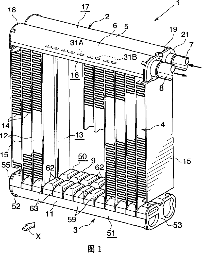
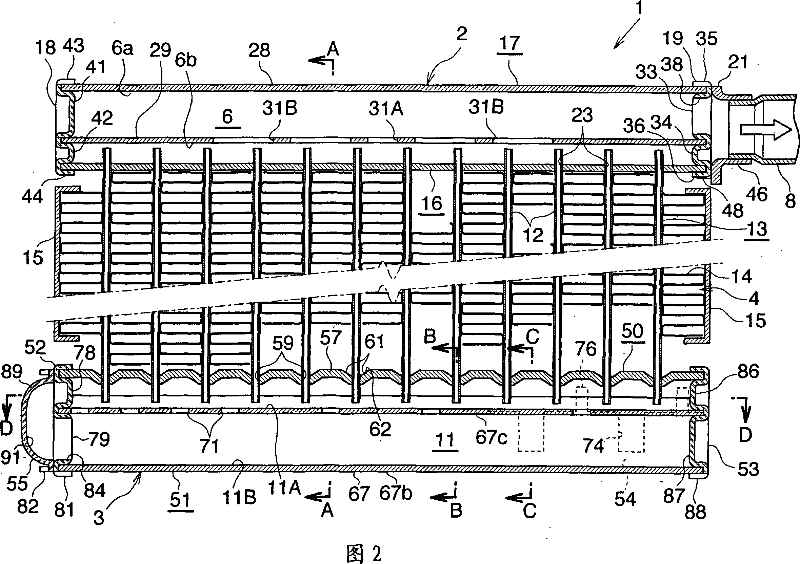
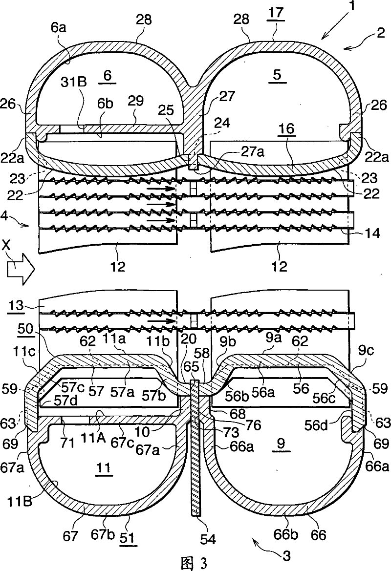
[0066] 1 to 3 show the overall structure of the evaporator, and FIGS. 4 to 10 show the structure of the main part of the evaporator. Figure 11 shows how the refrigerant flows in the evaporator.

[0067] In Figures 1 to 3, the evaporator (1) for a car air-conditioning unit using a refrigerant containing chlorofluorocarbons includes a refrigerant inlet-outlet box (2) made of aluminum and a refrigerant turning box (3) made of aluminum. ), the boxes (2) and (3) are vertically separated from each other, and also include a heat exchange core part (4) disposed between the boxes (2) and (3).

[0068] The refrigerant inlet-outlet box (2) includes a refrigerant inlet header portion (5) on the side toward the front (downstream side with respect to the air flow direction), and a refrigerant inlet header portion (5) on the side toward the rear (downstream side with respect to the air flow direction). The upstream side of the refrigerant outlet heade...

Embodiment 2

[0113] This embodiment is shown in FIG. 12 .

[0114] In the corrugated fin (14) of the evaporator of Embodiment 2, except for the cutout (95) and the inward protrusion ( 96), a notch (95) and an inward protrusion (96) are also formed on the front protruding portion (140) of the corrugated fin (14) protruding forward beyond the front end of the front flat tube (12).

[0115] Other structural features are the same as those of the evaporator (1) of Embodiment 1.

[0116] In the evaporator of Embodiment 2, when condensed water is generated on the surface of the corrugated fins (14), a part of the condensed water flows downward through the openings between the louver plates (94). In addition, condensed water flows toward the junction between the flat tube (12) and the crest portion (14a) and trough portion (14b) of the corrugated fin (14) under the action of surface tension, and collects on the junction. . Condensed water accumulated on the junction between the flat tube (12) a...

Embodiment 3

[0118] This embodiment is shown in FIG. 13 .

[0119] In the corrugated fins (14) of the evaporator of Embodiment 3, instead of the cutouts (95) and the inward protrusions ( 96), a notch (95) and an inward protrusion (96) are formed on the front protruding portion (140) of the corrugated fin (14) protruding forward beyond the front end of the front flat tube (12).

[0120] Other structural features are the same as those of the evaporator (1) of Embodiment 1.

[0121] In the evaporator of Embodiment 3, when condensed water is generated on the surface of the corrugated fins (14), a part of the condensed water flows downward through the openings between the louver plates (94). In addition, condensed water flows toward the junction between the flat tube (12) and the crest portion (14a) and trough portion (14b) of the corrugated fin (14) under the action of surface tension, and collects on the junction. . Condensed water accumulated on the junction between the flat tube (12) and...


PUM


Abstract

A corrugate fin 14 of an evaporator 1 includes wave crest portions 14a, wave trough portions 14b, and flat connection portions 14c connecting together the wave crest portions 14a and the wave trough portions 14b. Opposite end portions of a cutout 95 extend to corresponding connection portions 14c located at opposite ends of the wave crest portion 14a and the wave trough portion 14b. A projection 96 projecting inward is formed integrally with end portions of the connection portions 14c, the end portions of the connection portions 14c corresponding to opposite ends of the cutout 95. The projection 96 is formed in such a manner as to extend between the end portions of the connection portions 14c located at the opposite ends of the wave crest portion 14a and the wave trough portion 14c. The projection 96 projects inward in a shape resembling a lying letter V. The evaporator 1 exhibits excellent drainage of condensed water and enables high work efficiency in manufacture thereof.

Description

[0001] Cross References to Related Applications [0002] This application was filed pursuant to 35 U.S.C. §111(a) and required by 35 U.S.C. §119(e)(1) as provisional application No. 60 / 619,009 filed on October 18, 2004 pursuant to 35 U.S.C. §111(b) filing date benefits. technical field [0003] The present invention relates to an evaporator for a car air conditioner employing a refrigeration cycle to be installed, for example, on a vehicle. [0004] In the text and the appended claims, the upper, lower, left-hand and right-hand sides of Figures 1 and 2 are referred to as "upper", "lower", "left" and "right", respectively. The downstream side of the air flow (the side indicated by the arrow X in FIG. 1 and the right-hand side in FIG. 3 ) is called "front", and the opposite side is called "rear". Background technique [0005] A conventionally used evaporator for an automobile air conditioner includes: a plurality of refrigerant flow parts arranged in parallel; and corrugated...

Claims


Application Information

Patent Timeline
Patent Type & Authority Applications(China)
IPC IPC(8): F28F1/30F25B39/02F28D1/053
Inventor 东山直久鹤见幸弘
Owner SHOWA DENKO KK
Why Eureka
Try Eureka