Cooling storage

A storage room and storage room technology, which is applied to the field of cooling storage rooms, can solve the problems of complicated installation workability, poor workability, and difficult positioning of cooling units, and achieve the effects of easy installation work, improved installation workability, and cost realization.

Active Publication Date: 2007-09-26
SANYO ELECTRIC CO LTD
View PDF1 Cites 6 Cited by
  • Summary
  • Abstract
  • Description
  • Claims
  • Application Information

AI Technical Summary

Problems solved by technology

[0005] However, in the conventional structure as described above, since the cold air leaks from the gap between the upper opening of the cooling box and the cold air discharge port and the cold air suction port, after the mounting base is stored in the machine room, it is necessary to lift it up. Set up the cooling box equipped with the cooler and the blower for the cooler, and fix it to the bottom wall of the heat insulation box with fixing tools, etc.
Therefore, there is a problem that the installation workability of the cooling unit becomes complicated.
[0006] In addition, at this time, the cooling box must be fixed at a position corresponding to the cold air inlet and the cold air outlet formed on the bottom wall of the heat insulating box, and there is a problem that positioning is difficult and workability is further deteriorated.
In addition, it is also considered to raise the mounting base of each fixed cooling box and fix it to the bottom wall of the heat insulation box. However, since the mounting base is also equipped with equipment other than the cooling box such as a compressor and a condenser, Therefore, the total weight sometimes exceeds 40kg, and it is very troublesome to lift up every maintenance work, so I want to simplify the work

Method used


Image

  • Cooling storage
  • Cooling storage
  • Cooling storage

Examples


Embodiment Construction

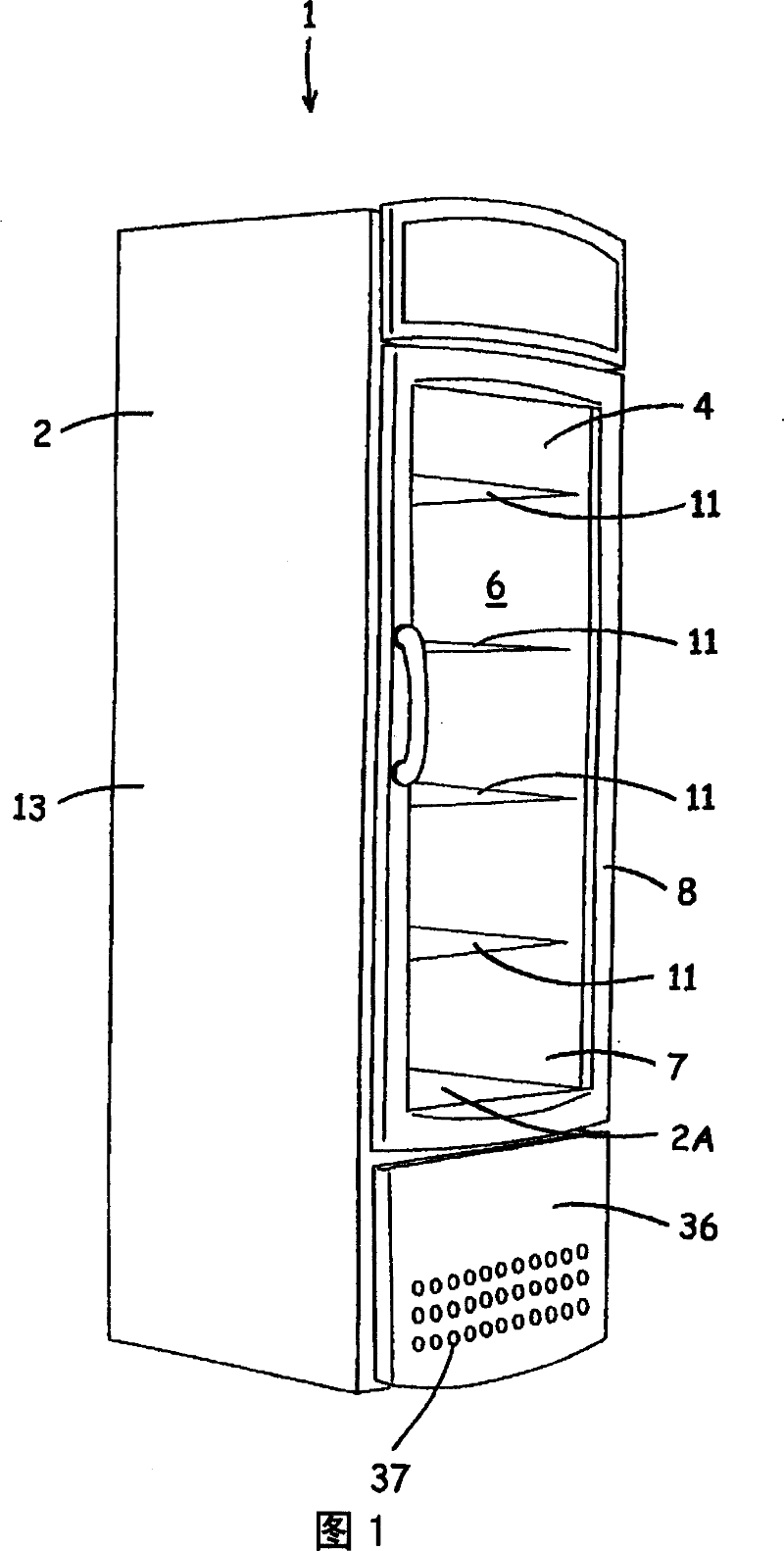
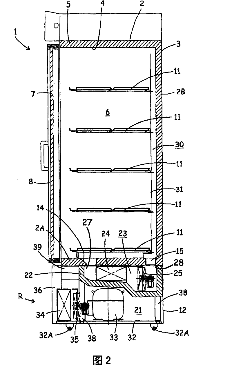
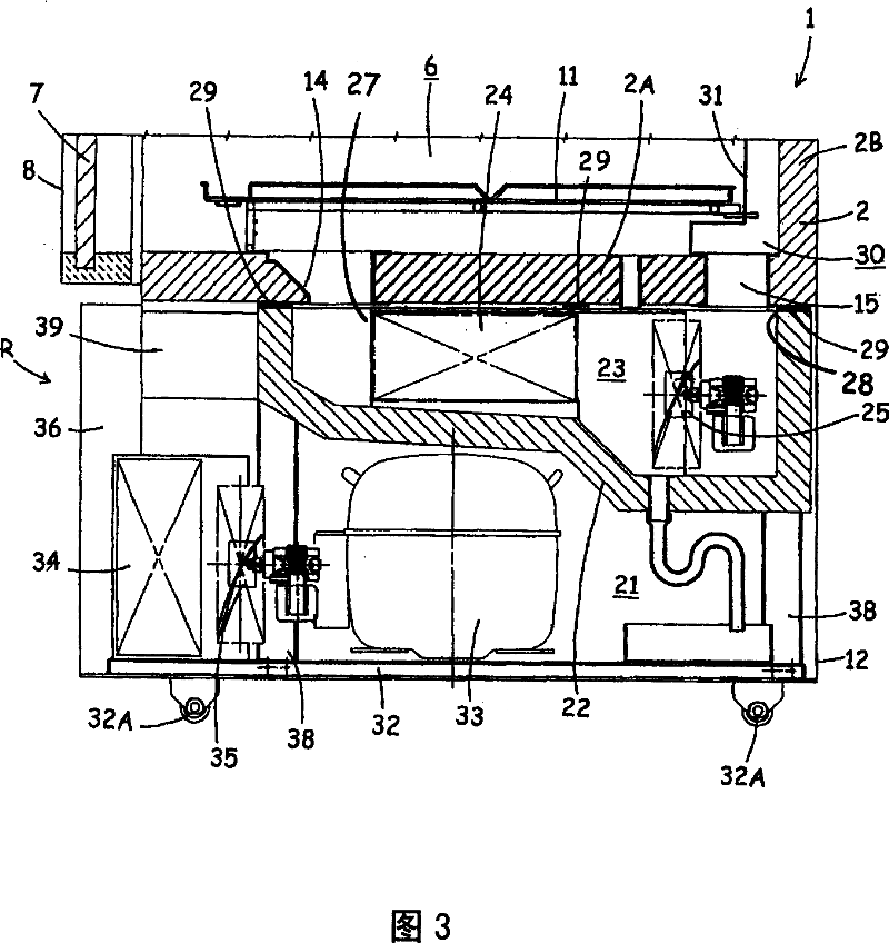
[0035] Hereinafter, cooling storage 1 according to the embodiment of the present invention will be described in detail based on the drawings. Fig. 1 is a perspective view of a cooling storage 1 to which the present invention is applied, Fig. 2 is a longitudinal sectional side view of the same cooling storage 1, and Fig. 3 is an enlarged longitudinal sectional side view of the lower part of Fig. 2 .

[0036] The cooling storage 1 of the present embodiment has a main body constituted by a rectangular heat insulating box 2 with an open front. The heat insulating box 2 is composed of an outer box 3 made of steel plate having an opening at the front, an inner box 4 having an opening at the front, and a heat insulating material 5 filled between the inner and outer boxes 3 and 4 with foam. In addition, a store room 6 with an open front is formed in the heat-insulating box 2 . The store room 6 is open at the front and is closably closed by a door 8 provided with glass 7 through which ...


PUM


Abstract

The invention provides a cooling storage reservoir. A cooling tank can be propped tightly on a bottom wall of an insulating container by pushing integrated cooling units, as the cooling tank. Cold air, which has the heat exchange with a cooler, can be discharged from a cold air outlet to a storeroom, and the cold air sucked from a cold air suction inlet to a cooling chamber can circulate for cooling the storeroom. The cooling storage reservoir comprises a limit part for positioning a cooling unit, so that the cold air outlet and the cold air suction inlet formed at the bottom wall of the insulating container can be corresponding to a lower side of the cold air outlet and the cold air suction inlet in the cooling tank; an ejection component, which can rotate freely and is propped on a lower surface at two sides of a soleplate or the lower surface of an inner side and a near front side, in the direction opposite to the direction of inserting the cooling unit to a mechanical den. The cooling unit is pushed to the direction of the bottom wall of the insulating container, and the ejection component is formed by bending a steel bar with a circular section.

Description

technical field [0001] The invention relates to a cooling storage house assembled under a heat-insulating box. The heat-insulating box is formed by a cooling unit composed of a compressor and a cooler inside to form a storage room. Background technique [0002] Conventionally, such cooling storages used as low-temperature showcases (showcases) have formed a machine room below the storage room formed in the heat-insulated box, and formed a cold air discharge port and a cold air outlet communicating with the machine room on the bottom wall of the heat-insulated box. Cold air intake. In the machine room, a cooling box having an opening on the upper surface is provided in contact with the bottom wall of the heat insulating box, and a cooler and a blower for the cooler constituting a cooling unit are arranged in the cooling box. And, the cooling box communicates with the storage room through the cool air inlet and the cool air discharge port. And, on the lower side of the cooli...

Claims


Application Information

Patent Timeline
Patent Type & Authority Applications(China)
IPC IPC(8): F25D19/00
Inventor 井口治信宫武俊明山口秀树辻谕米原悠二
Owner SANYO ELECTRIC CO LTD
Why Eureka
Try Eureka