
Hydraulic power generating device and manufacturing method therefor

A hydroelectric power generation device, one party's technology, applied in hydropower, electromechanical devices, final product manufacturing, etc., can solve problems such as rotation noise, shaft hole size error, shaft hole centering, etc., and achieve the effect of preventing rotation vibration and rotation noise

Active Publication Date: 2007-10-03
SANKYO SEIKI MFG CO LTD
View PDF1 Cites 4 Cited by
  • Summary
  • Abstract
  • Description
  • Claims
  • Application Information

AI Technical Summary

Problems solved by technology

In addition, since the water wheel for power generation is sprayed to the blades by the water ejected from the injection port and rotates, the positional relationship between the blades and the injection port changes with the rotation of the water wheel for power generation, and the direction of the force received by the water wheel for power generation changes. As a result, there is a problem that rotational vibration and rotational noise occur when the water wheel for power generation rotates
[0006] In addition, when the water wheel for power generation is integrally molded with radial bearings, due to the influence of shrinkage cavities, the high precision of the inner diameter of the shaft hole cannot be obtained, and there is a problem of rotation noise when the water wheel for power generation rotates.
In addition, when a structure in which radial bearings are integrally resin-molded at both ends of the cylindrical portion where the blades protrude from the outer peripheral surface is used, there may be errors in the shaft hole dimensions of each radial bearing due to the influence of shrinkage cavities.
In this state, since the concentricity between the shaft holes cannot be centered, although there is a large gap between the shaft hole and the support shaft of the radial bearing, once there is such a large gap When the water wheel for power generation rotates, there will be rotation noise

Method used


Image

  • Hydraulic power generating device and manufacturing method therefor
  • Hydraulic power generating device and manufacturing method therefor
  • Hydraulic power generating device and manufacturing method therefor

Examples


Embodiment Construction

[0025] Next, a hydroelectric power generation device to which the present invention is applied and a method of manufacturing the same will be described with reference to the drawings.

[0026] (the whole frame)

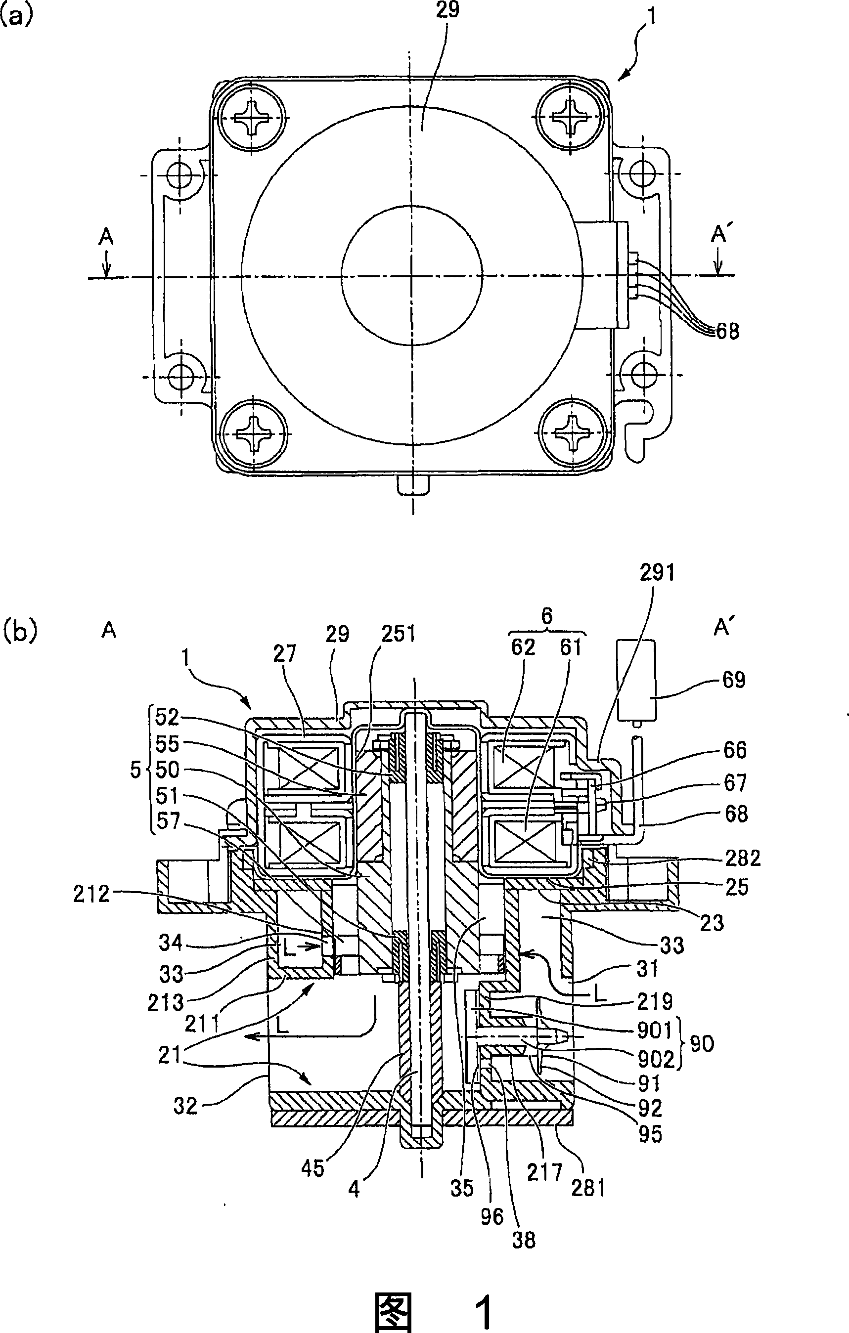
[0027]Fig. 1(a), (b) is a top view and A-A' sectional view of a hydroelectric power generation device to which the present invention is applied. The line A-A' does not pass through the position where the injection port is formed, and the left part of Fig. 1(b) also shows the injection port.

[0028] The hydroelectric power generation device 1 shown in Fig. 1 (a), (b) is a small hydroelectric power generation device arranged at a position in the middle of a water flow path, etc., and stores the electric power obtained by the hydroelectric power generation device 1, and uses the electric power Used in sensor circuits of automatic water faucets, etc. The hydroelectric power generation device 1 of this form has: a resin main body case 21 constituting a flow path describ...


PUM


Abstract

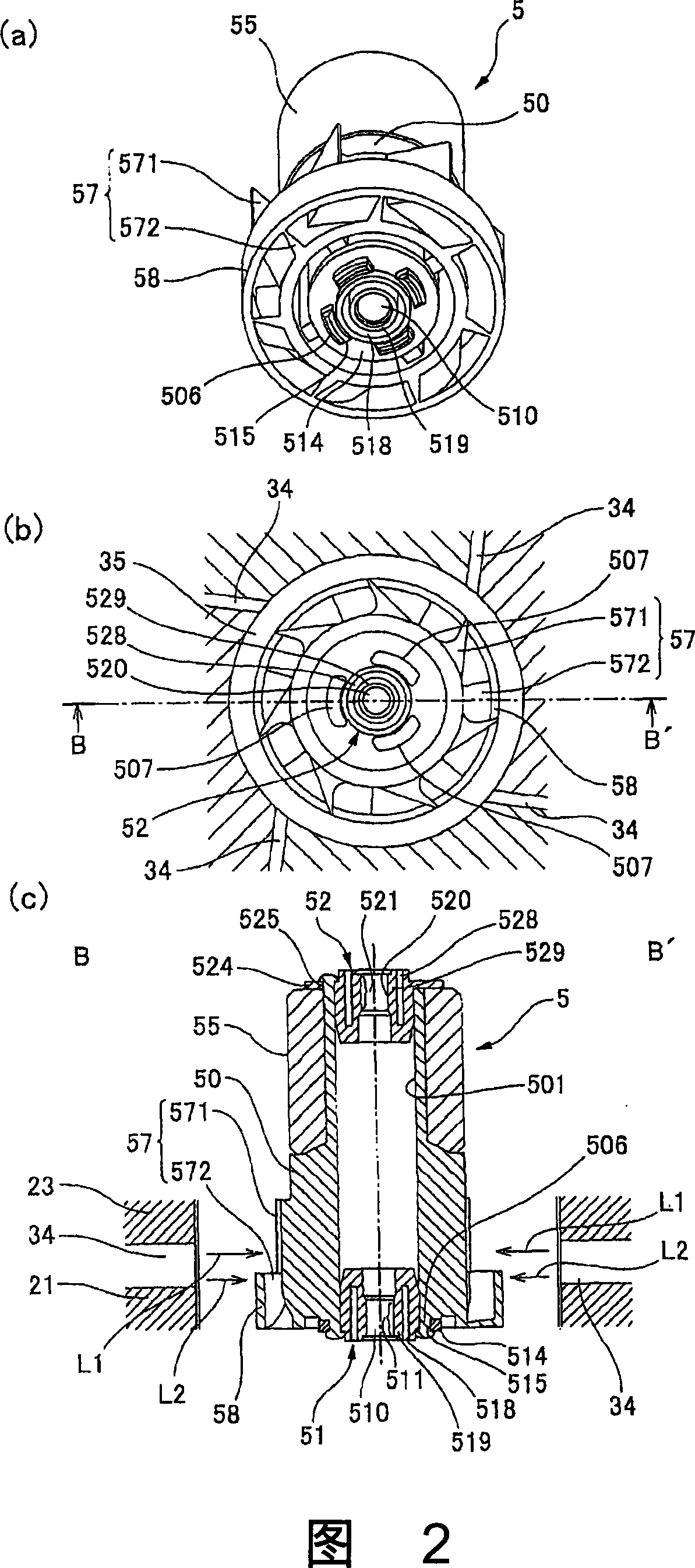
To provide a hydraulic power generating device capable of preventing rotation vibration and rotation noise when a water turbine for power generation is rotated. In a water turbine 5 for power generation of a hydraulic power generating device, a first blade 571 and second blade 572 are formed in an area adjacent to each other in an axial line direction. The outer peripheral ends of the second blades 572 are coupled by a cylindrical plate 58. Four ejection ports 34 are opened to a direction astride both the first blade 571 and cylindrical plate 58. A part of water ejected through an ejection port 34 directly collides with the first blade 571. The rest continuously collides with the outer end surface of the cylindrical plate 58 from each direction. Thus, aligning action is exerted to the water turbine 5 for power generation. The number of ejection ports 34 and the number of blades 57 are prime to each other. Since timings at which four first blades 571 come nearest to the ejection ports 34 respectively are deviated, water ejected through the ejection port 34 is prevented from intensely colliding with two or more blades 57 at the same time.

Description

technical field [0001] The present invention relates to a hydroelectric power generation device for generating power using tap water or the like, and a method for manufacturing the same. Background technique [0002] There is an automatic faucet device that is becoming popular: when the hand is put under the faucet, as soon as the sensor senses this situation, water will automatically flow from the faucet. In addition, in recent years, it has been proposed to install a small hydroelectric power generation device in the middle of the water flow path, store the electric power obtained by the hydroelectric power generation device, and supply the electric power to the sensor circuit of the automatic faucet device, etc. [0003] Such a hydroelectric power generation device has: a housing forming a flow path from a fluid inlet to a fluid outlet; a support shaft disposed in the middle of the flow path; a cylindrical power generating water rotatably supported on the support shaft. ...

Claims


Application Information

Patent Timeline
Patent Type & Authority Applications(China)
IPC IPC(8): F03B13/00H02K7/18
CPCY02E10/223Y02E10/28Y02E10/20Y02P70/50
Inventor 田中彰吾弓田行宣伊藤秀明吉川伸一
Owner SANKYO SEIKI MFG CO LTD
Learn More