
Cable fixture

A technology for fixing devices and cables, which is applied in the direction of coupling devices, two-part connecting devices, elastic/clamping devices, etc., and can solve problems such as flexible cable application, large stress, and device performance degradation

Inactive Publication Date: 2007-10-03
SONY GRP CORP
View PDF2 Cites 9 Cited by
  • Summary
  • Abstract
  • Description
  • Claims
  • Application Information

AI Technical Summary

Problems solved by technology

For example, there are situations where a flexible cable for connection between a device and a connector passes through an opening portion of a shielded metal plate, and at this time it is necessary to provide a conductive connection between the cable and the shielded metal plate to solve EMC problems, further , the deformation of the flex cable resulting from the conductive connection of the flex cable to the shielded metal plate will place a large stress on the flex cable, which may result in degraded device performance

Method used


Image

  • Cable fixture
  • Cable fixture
  • Cable fixture

Examples


Embodiment Construction

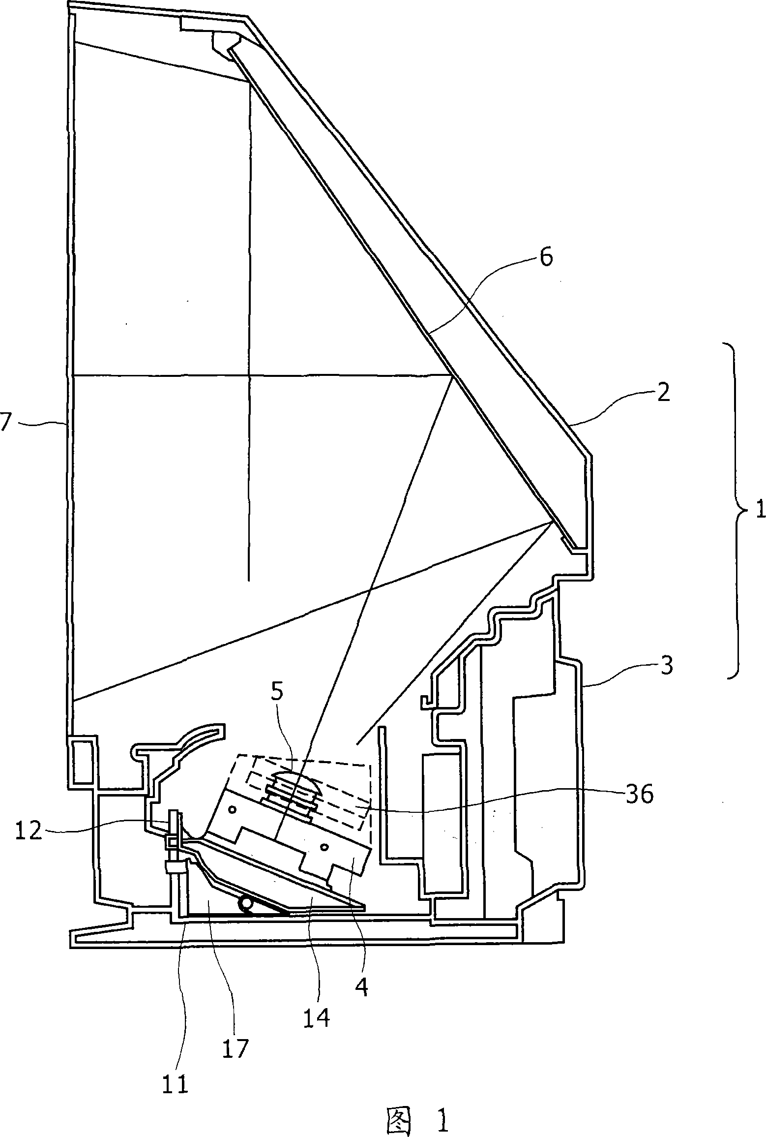
[0041] Embodiments of the cable fixing device of the present invention will be described below with reference to FIGS. 1-23 . Hereinafter, an example in which the cable fixing device is applied to the rear projection display device in this embodiment will be described by taking the rear projection display device as an electronic device using the cable fixing device.

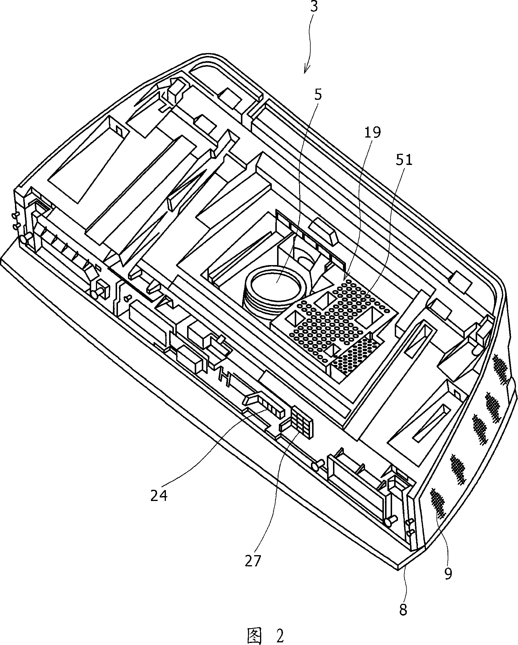
[0042] FIG. 1 is a side view showing the general internal configuration of a rear projection display device, and FIG. 2 is a perspective view of a bottom cabinet.

[0043] The cabinet 1 constituting the casing of the rear projection display device is composed of two parts, including a top cabinet 2 located above and a bottom cabinet 3 located below in FIG. 1 . The reflector 6 and the screen 7 are arranged in the top box 2, and the optical unit 4 is arranged in the bottom box 3, and the optical unit 4 is used to modulate the luminous flux emitted by the light source (not shown) to form an optical image according t...


PUM


Abstract

A cable fixture including a holding section for holding a cable relative to a chassis; and a fitting section formed integrally with the holding section and operative to fix the holding section to the chassis, wherein the cable is fitted, from one side, to and hooked on a hole provided in the vicinity of an opening formed in the chassis for permitting the cable to pass therethrough, by the fitting sections provided at both end portions of the holding section, and the wiring direction of the cable fixed by the holding section coincides substantially with the fixing direction in fixation of the chassis by the fitting sections.

Description

technical field [0001] The present invention relates to a cable fixing device for installing cables and the like to a chassis of electronic equipment and the like. Background technique [0002] As a cable fixing device for fixing a flat cable to a chassis made of a metal plate, there is known a fixing device disclosed in Japanese Patent Laid-Open No. 2004-239325 (hereinafter referred to as Patent Document 1). [0003] Patent Document 1 describes a fixing device for mounting electronic components, cables, etc. to a chassis of electronic equipment and the like, and allowing easy detachment operations from the surface side of the chassis. [0004] The fixing device has a holding portion for holding the component on the chassis, and a mounting portion integrally formed with the holding portion and for fixing the holding portion to the chassis. The mounting part has a base, a clamping piece and a locking body, wherein the base has a flat bottom surface capable of coming into con...

Claims


Application Information

Patent Timeline
Patent Type & Authority Applications(China)
IPC IPC(8): F16B5/10H02G3/30H05K7/12
CPCH01R23/661H01R12/772F16B5/10H02G3/24
Inventor 小野木佑
Owner SONY GRP CORP
Learn More