Digital telescope system with great field depth

A telescope and telescopic objective lens technology, applied in the field of optics, can solve the problems of time-consuming and resource-consuming, and achieve the effect of low processing cost, large processing tolerance, and large degree of freedom

Inactive Publication Date: 2007-10-03
ZHEJIANG JINCHENG SCI & TECH
View PDF0 Cites 10 Cited by
  • Summary
  • Abstract
  • Description
  • Claims
  • Application Information

AI Technical Summary

Problems solved by technology

Post-stage digital image processing is time-consuming and resource-consuming

Method used


Image

  • Digital telescope system with great field depth
  • Digital telescope system with great field depth
  • Digital telescope system with great field depth

Examples


Embodiment 1

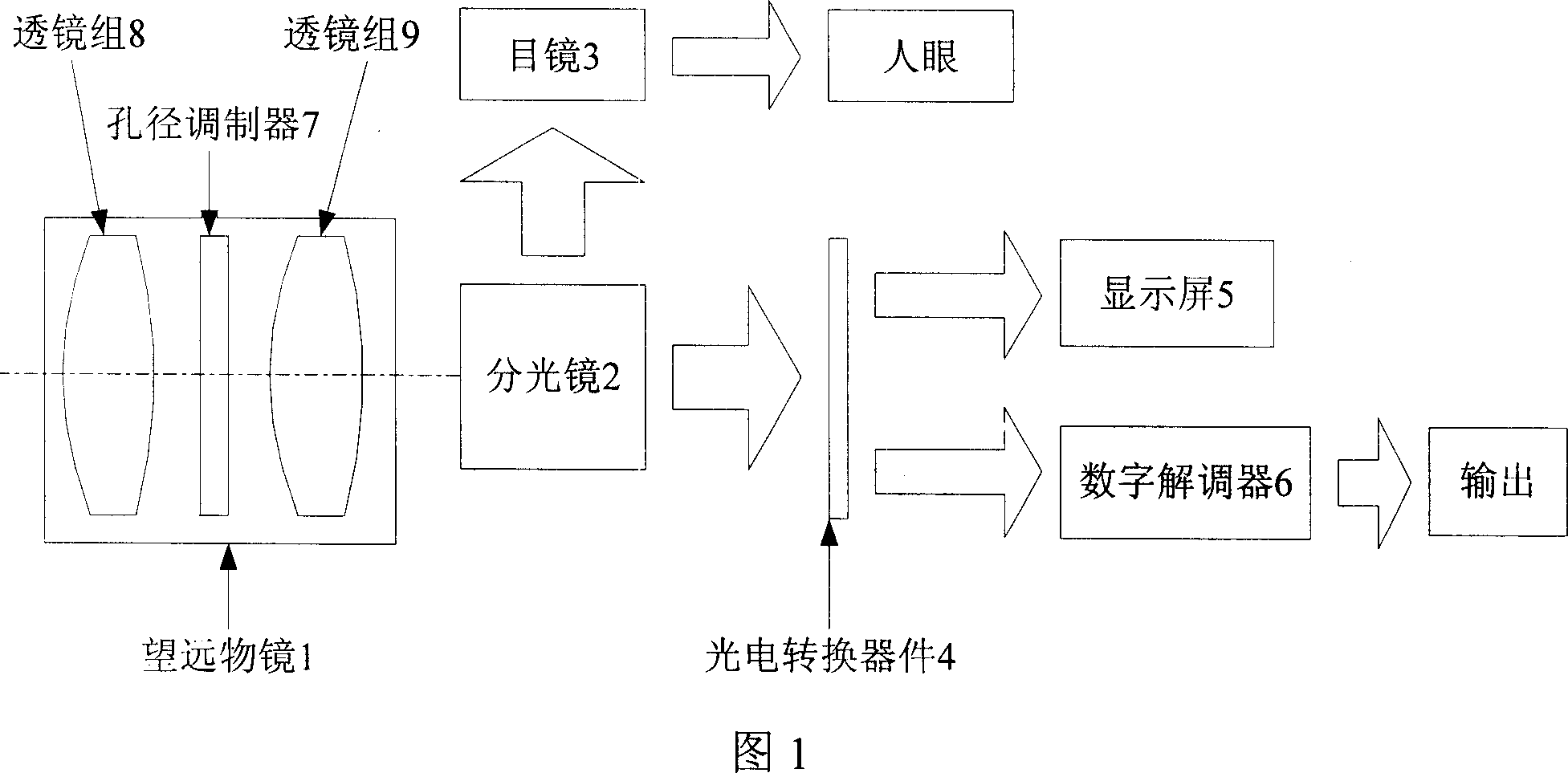
[0031] The basic parameters of the large depth of field digital telescope system shown in Figure 1 are as follows, F# is 3, the effective focal length is 280 mm, and the object field angle is 1.8 degrees. In an embodiment, the mathematical expression of the aperture modulator is:

[0032] z(x,y)=-5.081×10 -5 x 2 -5.0355×10 -5 the y 2 +3×10 -7 x 3 +3×10 -7 the y 3

[0033] -2.0556×10 -10 x 4 -2.5979×10 -10 the y 4

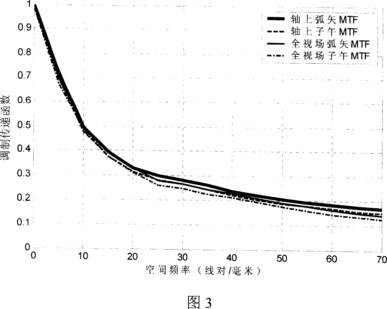
[0034] When illuminated by an incoherent light source, the modulation transfer function curves of the sagittal meridional direction of the large depth-of-field digital telescopic objective lens at infinity object distance, 1000 m object distance and 150 m object distance are shown in Fig. Shown in Fig. 5 and Fig. 7; For comparison, under the object distance of infinity, 1000 meter object distance and 150 meter object distance of traditional digital telescopic objective lens, the modulation transfer function curves of their sagittal meridional d...


PUM


Abstract

The digital telescope system with great field depth includes one telescope objective, one beam splitter to divide the output light beam into two light beams, one eye lens, one photoelectric converting device, one display screen and one digital demodulator connected to the output terminal. Inside the telescope barrel, is one aperture modulating tab with one side meeting the equation of z(x, y)=ax2+by2+cx3+dy3+ex4+fy4. The digital telescope system with great field depth utilizes the aperture modulating tab to modulate the pupil function so as to compensate the aberration caused by view field change and expand the field depth. The present invention has simple structure, low cost, no decrease on light flux and no need of focusing.

Description

technical field [0001] The invention relates to a digital telescope system with a large depth of field, belonging to the field of optical technology. Background technique [0002] The first telescope was born in Europe in the 17th century. After nearly 400 years of development, the imaging quality of telescopes has been improving day by day. Especially at the end of the last century, the wide application of photoelectric conversion devices and the continuous updating of digital processing technology injected new vitality into this ancient subject. [0003] Telescope technology is widely used in military detection, astronomical observation, criminal investigation and so on. The image formed by a distant object through the telescope objective lens can be observed through the eyepiece, or the information of the distant object can be converted into a data stream through a photoelectric conversion device, and output to a display or printing terminal. [0004] Small depth of fi...

Claims


Application Information

Patent Timeline
Patent Type & Authority Applications(China)
IPC IPC(8): G02B13/02G02B23/00
Inventor 赵廷玉张文字叶子陆祖康宁志高余飞鸿
Owner ZHEJIANG JINCHENG SCI & TECH
Why Eureka
Try Eureka