Digital microscope system with large DOF (depth of field)

A microscope system and digital technology, applied in the field of optics, can solve the problems of reducing the amount of light passing, reducing the resolution, and taking a long time to achieve the effect of large processing tolerance, low focusing accuracy requirements and good compatibility.

Inactive Publication Date: 2015-01-14
ZHEJIANG SCI-TECH UNIV
View PDF3 Cites 0 Cited by
  • Summary
  • Abstract
  • Description
  • Claims
  • Application Information

AI Technical Summary

Problems solved by technology

The first type is to perform amplitude modulation on the aperture of the optical system, which is represented by reducing the relative aperture, but this method is at the expense of reducing the amount of light passing through and reducing the resolution
The second type is to scan each imaging surface by means of confocal imaging, and finally achieve it by means of digital image reconstruction. This method requires a special precision motor to complete the scan, which is costly and time-consuming
The third category is to expand the depth of field through wavefront coding technology, which adds a φ=α(x 3 +y 3 ) phase plate, and then digitally filter the image obtained on the photoelectric conversion device CCD or photoelectric conversion device CMOS, so as to meet the requirement of expanding the depth of field, it needs to redesign, process and manufacture the entire microscopic system, and the cost is relatively high high

Method used


Image

  • Digital microscope system with large DOF (depth of field)
  • Digital microscope system with large DOF (depth of field)
  • Digital microscope system with large DOF (depth of field)

Examples


Embodiment 1

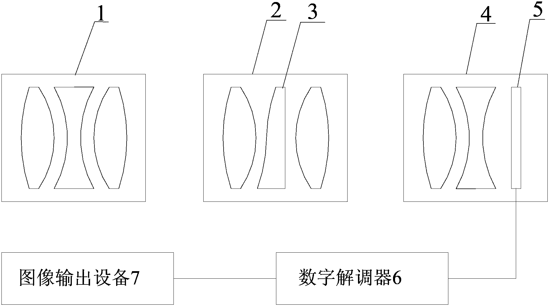
[0050] Such as Figure 5 As shown, it is the large depth of field digital microscope system of the present invention figure 1 structure based on the example. The large depth of field digital microscope system of the present invention comprises a microscope objective lens 1, an electronic eyepiece 4 with a photoelectric conversion device 5, and a digital demodulator connected with the photoelectric conversion device 5 ( Figure 5 not shown in ) and the image output device connected to the digital demodulator ( Figure 5 Not shown in ), all adopt the prior art, 12 is the sample to be observed, a depth of field extender 2 is provided between the microscope objective lens 1 and the electronic eyepiece 4, and the depth of field extender 2 includes a front lens 8 and a rear lens 9 And the phase mask 3 that is arranged between the front lens 8 and the rear lens 9, the depth of field extender 2 is made of an optical 4f system and the phase mask 3, wherein the optical 4f system is co...


PUM


Abstract

The invention discloses a digital microscope system with large DOF (depth of field), and relates to the technical field of optics. The digital microscope system comprises a microscope objective, an electronic eyepiece provided with a photoelectric conversion device, a digital demodulator connected with the photoelectric conversion device, and an image output device connected with the digital demodulator. The digital microscope system is characterized in that a DOF extension device is arranged between the microscope objective and the electronic eyepiece, and is provided with a phase mask; one side of the phase mask meets an equation (1): z(x, y)=ax<3>+by<3>+cx<4>+dy<4>+ex<2>y<2>+fxy<2>+gx<3>y, wherein a, b, c, d, e, f and g are factors, and x, y and z (x,y) are respectively x-axis position, y-axis position, and z-axis position of any point on the phase mask surface that meets the equation (1) in a three-dimensional Cartesian coordinate system; and the three-dimensional Cartesian coordinate system takes the center of the phase mask as the origin of coordinates and takes an optical axis as z axis. The digital microscope system with the large DOF realizes the large DOF function through the additional DOF extension device without breaking a main part structure of a traditional digital microscope system, and has the advantages of low cost, good compatibility and the like.

Description

technical field [0001] The invention relates to the field of optical technology, in particular to a digital microscope system with a large depth of field. Background technique [0002] Since the optical microscope was invented in Europe at the end of the 16th century, it has expanded human vision to a whole new world. Microscope technology has a wide range of applications in biology, medicine, industry and many other fields. After more than 400 years of development, the imaging quality of microscopes has been improving day by day. Especially at the end of the last century, the wide application of photoelectric conversion devices and the continuous updating of digital processing technology injected new vitality into this ancient subject. [0003] The existing digital microscope system includes a microscope objective lens, an electronic eyepiece with a photoelectric conversion device, a digital demodulator connected to the photoelectric conversion device, and an image output...

Claims


Application Information

Patent Timeline
Patent Type & Authority Patents(China)
IPC IPC(8): G02B21/36G02B27/00
Inventor 赵廷玉刘爱萍刘钦晓余飞鸿
Owner ZHEJIANG SCI-TECH UNIV
Why Eureka
Try Eureka