Force imaging input device and system

An imaging and image technology, applied in the field of force imaging and mutual capacitance system of position and force imaging

Active Publication Date: 2007-10-03
APPLE INC
View PDF2 Cites 92 Cited by
  • Summary
  • Abstract
  • Description
  • Claims
  • Application Information

AI Technical Summary

Problems solved by technology

[0004] One disadvantage of using touchpads as input devices

Method used


Image

  • Force imaging input device and system
  • Force imaging input device and system
  • Force imaging input device and system

Examples


Embodiment Construction

[0019] The following description is made to enable a person skilled in the art to carry out and utilize the invention as claimed, and is provided for the specific example discussed below (a touch panel input device for a personal computer system), with various modifications thereof. It will be obvious to those skilled in the art. Thus, the appended claims are not limited to the disclosed embodiments, but are to be accorded the widest scope consistent with the principles and features disclosed herein. For example, the force imaging system according to the present invention is equally applicable to electronic devices that are not personal computer systems, such as computer workstations, mobile phones, handheld digital assistants, and in various (chemical, electrical, and electronic) machines and systems digital control panel.

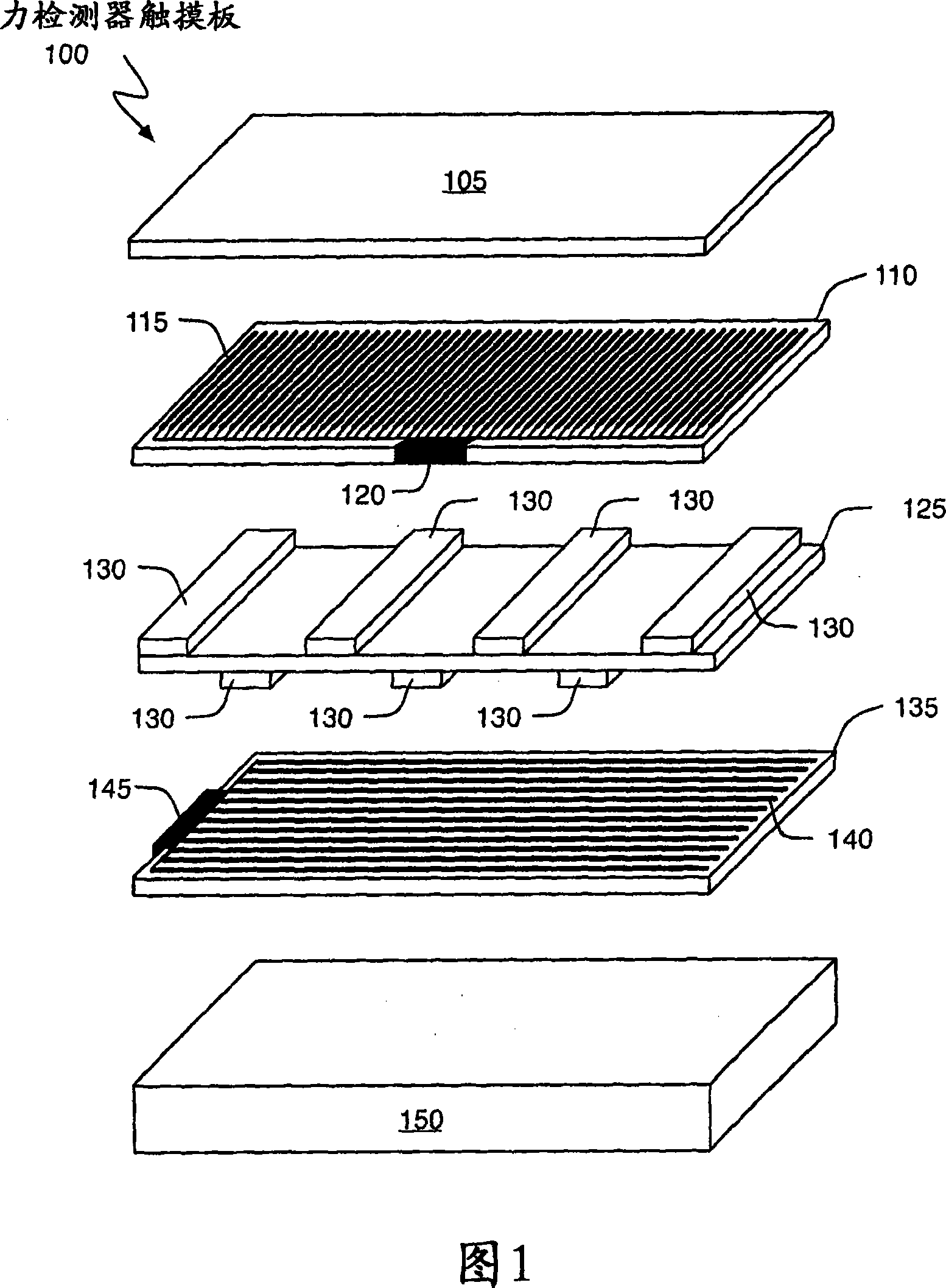
[0020] Referring to FIG. 1 , the general concept of a force detector according to the present invention is illustrated as it can be implemented in a tou...


PUM


Abstract

A force imaging touch pad includes first and second sets of conductive traces separated by a spring membrane. When a force is applied, the spring membrane deforms moving the two sets of traces closer together. The resulting change in mutual capacitance is used to generate an image indicative of the amount or intensity of the applied force. A combined location and force imaging touch pad includes two sets of drive traces, one set of sense traces and a spring membrane. In operation, one of the drive traces is used in combination with the set of sense traces to generate an image of where one or more objects touch the touch pad. The second set of drive traces is used in combination with the sense traces and spring membrane to generate an image of the applied force's strength or intensity.

Description

technical field [0001] The present invention relates generally to electronic system input devices, and more particularly to force imaging and position and force imaging mutual capacitance systems. Background technique [0002] There are many touch-sensing devices available in computer systems, personal digital assistants, mobile phones, gaming systems, music systems, etc. (eg, electronic systems). Probably the best known are resistive diaphragm position sensors, which have been used for many years as keypads and position indicators. Other types of touch sensitive devices include resistive writing tablets, surface acoustic wave devices, resistive, capacitive based touch sensors, strain gauges, electromagnetic or pressure sensors, and optical sensors. Pressure-sensitive position sensors have had little use advantage in the past as pointing devices (as opposed to data entry or writing devices) because the pressure required to make them operate inherently creates stiction betwe...

Claims


Application Information

Patent Timeline
IPC IPC(8): G06F3/044
CPCG06F3/044G06F3/0414G06F3/04166G06F3/0447G06F3/0446G06F3/0445G06F2203/04101G06F2203/04105G06F2203/04106G06F2203/04112
Inventor 斯蒂文·P·豪泰灵布赖恩·Q.·赫普
Owner APPLE INC
Why Eureka
Try Eureka