1-3.5T gap buffer lift oil cylinder with one-way valve at cylinder bottom

A technology for lifting cylinders and one-way valves, which is applied to lifting devices, fluid pressure actuating devices, etc., can solve the problems of reducing the stability of hydraulic parts, reducing the working area of ​​hydraulic oil, and being unfavorable for forklifts to work. Good for heat balance, lower hydraulic oil temperature, and simple structure

Active Publication Date: 2007-10-10
ANHUI HELI CO LTD
View PDF0 Cites 8 Cited by
  • Summary
  • Abstract
  • Description
  • Claims
  • Application Information

AI Technical Summary

Problems solved by technology

However, although the existing form of oil cylinder buffer mechanism solves the buffer problem of the oil cylinder descending, there is an unavoidable problem-rising throttling
The rising throttling reduces the lifting efficiency and the lifting speed to a certain extent; at the same time, during the rising buffer period, the actual working area of ​​the hydraulic oil is greatly reduced, and the working oil temperature is objectively increased. Reduce the stability of the hydraulic parts, which is not conducive to the work of the forklift

Method used


Image

  • 1-3.5T gap buffer lift oil cylinder with one-way valve at cylinder bottom
  • 1-3.5T gap buffer lift oil cylinder with one-way valve at cylinder bottom

Examples


Embodiment

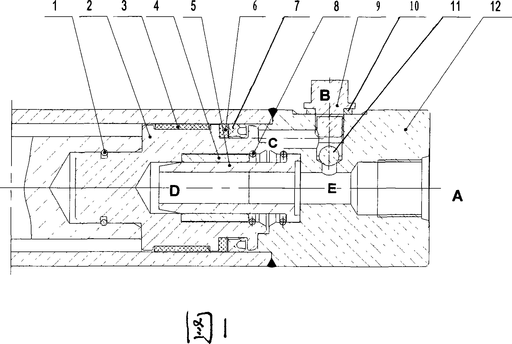
[0017] The 1-3.5T gap buffer lifting cylinder with cylinder bottom check valve includes cylinder body, piston 2, spool 5 and cylinder bottom 12. The spool 5 is located in the spool hole corresponding to the piston 2 and the cylinder bottom, and the spool 5 corresponds to the oil passage at the bottom of the cylinder 12, the piston 2 is set with a piston steel wire retaining ring 1, the support ring 3, a U-shaped sealing ring 6 and a retainer 7, and the valve core 5 is set with a copper sleeve 4 and a steel wire retaining ring 8, see picture 1.

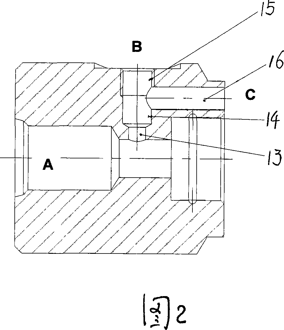
[0018] There is a small through hole 13 radially on one side of the oil passage at the bottom of the cylinder 12, the small through hole 13 is coaxially connected to the steel ball hole 14 and the threaded hole 15, perpendicular to the steel ball hole 14, and a cylinder bottom 12 with a piston 2 Corresponding to the bypass oil channel 16 at the bottom, the steel ball 11 is fitted in the steel ball hole 14 to act as a one-way valve, and...


PUM


Abstract

The present invention relates to a 1-3.5T intermittent buffered lifting hydraulic cylinder with cylinder bottom non-return valve. It is an improvement on existent lifting hydraulic cylinder structure, and its improvement lies in that on the radial direction of oil groove side of cylinder bottom a small through hole is cut, said small through hole and shaft are connected with steel bal hole and threaded hole, and on the cylinder bottom a by-pass oil groove is set, and said by-pass oil groove is correspondent to the piston bottom portion, and in the steel ball hole a steel ball is mounted.

Description

technical field [0001] The invention relates to a lifting oil cylinder used in a small-tonnage forklift lifting system. Background technique [0002] At this stage, a considerable part of the lifting cylinders used in the lifting system of small-tonnage forklifts adopts a gap buffer mechanism to achieve the purpose of descending buffer. The principle of the gap buffer oil cylinder is to use the form of hydraulic throttling to control the return flow of hydraulic oil, thereby reducing the descending speed of the cargo and eliminating the noise caused by the descending impact. Due to its simple principle, convenient manufacture and low cost, the gap buffer has a wide range of applications. But the oil cylinder buffering mechanism of existing form has solved the buffering problem of oil cylinder descending, but there is an unavoidable problem—rising throttling. The rising throttling reduces the lifting efficiency and the lifting speed to a certain extent; at the same time, du...

Claims


Application Information

Patent Timeline
Patent Type & Authority Applications(China)
IPC IPC(8): F15B15/14F15B15/22B66F9/06
Inventor 马庆丰周齐齐钟继萍王旭兵
Owner ANHUI HELI CO LTD
Why Eureka
Try Eureka