Remote control lift lamp

A technology of lifting lights and elevators, which is applied in the field of lifting lights, can solve problems such as unsafe operation, high maintenance costs, and difficult maintenance of high-altitude lighting, and achieve the effects of simple operation, convenient maintenance, and accurate docking

Inactive Publication Date: 2007-10-10
上海必金灯具有限公司
View PDF0 Cites 15 Cited by
  • Summary
  • Abstract
  • Description
  • Claims
  • Application Information

AI Technical Summary

Problems solved by technology

[0003] The technical problem to be solved by the present invention is to provide a remote control lifting lamp, which overcomes the disadvantages of difficult maintenance of high-altitude lamps, high maintenance costs and unsafe operation

Method used


Image

  • Remote control lift lamp
  • Remote control lift lamp
  • Remote control lift lamp

Examples


Embodiment Construction

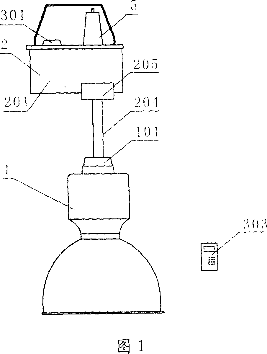
[0019] As shown in Figure 1 and Figure 2: a remote control lifting lamp, including a lighting lamp 1, a lift 2, and a remote control device.

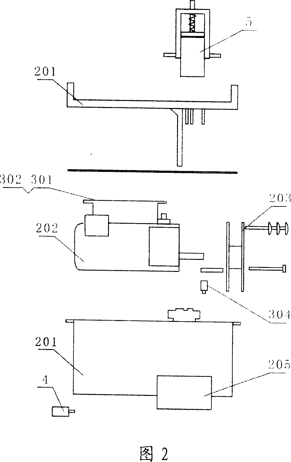
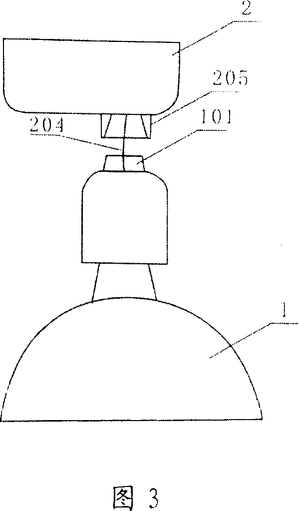
[0020] Wherein the elevator 2 is composed of a casing 201 , a forward and reverse motor 202 inside the casing 201 , and a reel 203 arranged on the rotating shaft of the forward and reverse motor 202 . A wire rope 204 is wound on the reel 203, and the lighting lamp 1 is tied to the end of the wire rope 204. An interface 205 is provided at the bottom of the casing 201 of the elevator 2 and a joint 101 connected with the interface 205 of the elevator 2 is provided at the top of the lighting lamp 1 . Conductive contacts 206 and 102 are provided in the interface 201 and on the connector 101 , as shown in FIG. 4 and FIG. 5 .

[0021] The remote control device as shown in FIG. 2 and FIG. 4 includes a signal receiver 301 , a power supply 302 , a signal transmitter 303 (remote controller), and a travel switch 304 . The signal receiver 301 and ...


PUM


Abstract

A rising-and-falling lamp of remote control type is prepared for forming lifter by shell and forward-backward rotation motor as well as winding wheel set on shaft of said motor, hanging illumination lamp on steel wire rope wound on said winding wheel and forming remote control unit by signal receiver set in shell of lifter and power supply as well as hand signal emitter.

Description

technical field [0001] The invention relates to a lighting device, in particular to a lift lamp. Background technique [0002] The indoor lighting fixtures of tall buildings at home and abroad are all fixedly installed on the top of the house now. The biggest difficulty of the existing lighting fixtures is the difficulty of maintenance. The lighting fixtures must be maintained at high altitudes by means of special lifting equipment or by setting up scaffolding and aisles in the air. The above-mentioned maintenance methods are not only cumbersome, but also extremely unsafe, and the maintenance cost is high. In some special environments, maintenance cannot be implemented at all, and the maintenance of lamps is extremely inconvenient. Contents of the invention [0003] The technical problem to be solved by the present invention is to provide a remote-controlled lifting lamp, which overcomes the disadvantages of difficult maintenance of high-altitude lamps, high maintenance co...

Claims


Application Information

Patent Timeline
Patent Type & Authority Applications(China)
IPC IPC(8): F21V21/38G08C17/02H05K7/00
Inventor 刘必金
Owner 上海必金灯具有限公司
Why Eureka
Try Eureka