Signal isolation transfer circuit

A signal isolation and circuit technology, applied in signal transmission systems, electrical signal transmission systems, instruments, etc., can solve the problem of high cost

Active Publication Date: 2007-10-10
VERTIV CORP
View PDF0 Cites 11 Cited by
  • Summary
  • Abstract
  • Description
  • Claims
  • Application Information

AI Technical Summary

Problems solved by technology

[0003] Aiming at the above-mentioned defects of the prior art, the present invention solves the problem that the circuit for isolating and transmitting analog signals in the prior art has a relatively high cost due to the need to use a linear optocoupler, and provides a signal that can use an ordinary optocoupler. isolated transmission circuit

Method used


Image

  • Signal isolation transfer circuit
  • Signal isolation transfer circuit
  • Signal isolation transfer circuit

Examples


Embodiment Construction

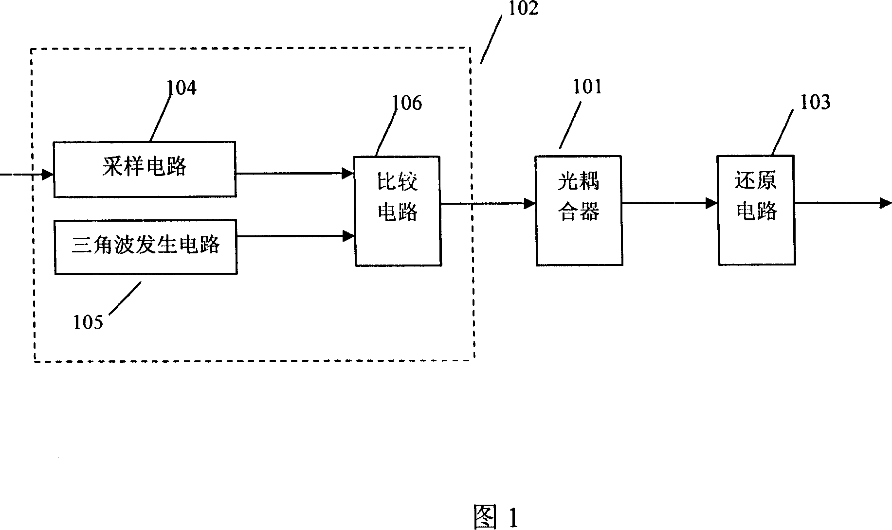
[0019] The principle of the signal isolation transmission circuit of the present invention is shown in FIG. 1, where the sampling circuit 104, the triangle wave generating circuit 105 and the comparison circuit 106 constitute the aforementioned modulation circuit 102. When working, the sampling circuit 104 first samples the analog signal to obtain the input analog signal and send it to the comparison circuit 106; at the same time, the triangle wave generating circuit 105 provides a triangle wave signal to the comparison circuit; the comparison circuit 106 according to the input analog signal and the triangle wave signal, An input PWM signal is provided to the primary side of the optocoupler 101; after the optocoupler transmits the PWM signal to the secondary side, it is converted by the restoration circuit 103 to obtain a restored analog signal.

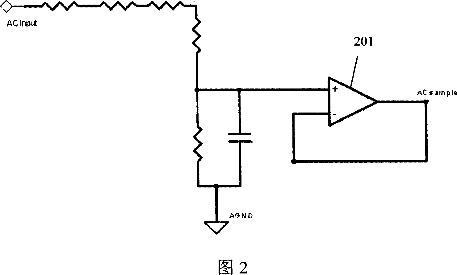
[0020] Figure 2 is a schematic diagram of the sampling circuit in a preferred embodiment of the present invention, in which the voltage...


PUM


Abstract

The present invention relates to a signal isolated transfer circuit capable of using general optical coupler. In said invention, firstly a sampling circuit is used to make sampling to obtain input analog signal, then the input analog signal is transferred to a comparison circuit; at the same time a triangular-wave generator is used for providing triangular-wave signal for said comparison circuit, then according to input analog signal and triangular-wave signal the comparison circuit can provide input PWM signal for primary side optical coupler, after the input PWM signal is transferred to the secondary side by optical coupler, a reduction circuit is used for making conversion so as to obtain reduced analog signal.

Description

Technical field [0001] The present invention relates to an AC and DC voltage signal isolation transmission technology, and more specifically, to a signal isolation transmission circuit that can use a common optical coupler. Background technique [0002] When the AC and DC voltage analog signal needs to be transmitted across the primary and secondary side, in the prior art, the sampled analog signal is generally obtained first, then transmitted to the other side through a linear optical coupler or transformer, and finally restored. The disadvantage of using a transformer is that it cannot transmit a DC signal; the disadvantage of using a linear optical coupler is its high cost, due to its high precision and high cost, and the use of an ordinary optical coupler cannot meet the needs of analog signal transmission. Summary of the invention [0003] In view of the above-mentioned shortcomings of the prior art, the present invention solves the problem that the circuit used for isolati...

Claims


Application Information

Patent Timeline
Patent Type & Authority Applications(China)
IPC IPC(8): G08C19/36
Inventor 朱春辉黄晶晶甘松柏
Owner VERTIV CORP
Why Eureka
Try Eureka