
Thin film transistor array base board and its repairing method

A technology for thin film transistors and array substrates, which is applied in the field of thin film transistor array substrates and their repairs, can solve problems such as inability to repair, and achieves the effects of not affecting the aperture ratio and being convenient and simple to repair.

Inactive Publication Date: 2007-10-10
NANJING CEC PANDA LCD TECH
View PDF1 Cites 21 Cited by
  • Summary
  • Abstract
  • Description
  • Claims
  • Application Information

AI Technical Summary

Problems solved by technology

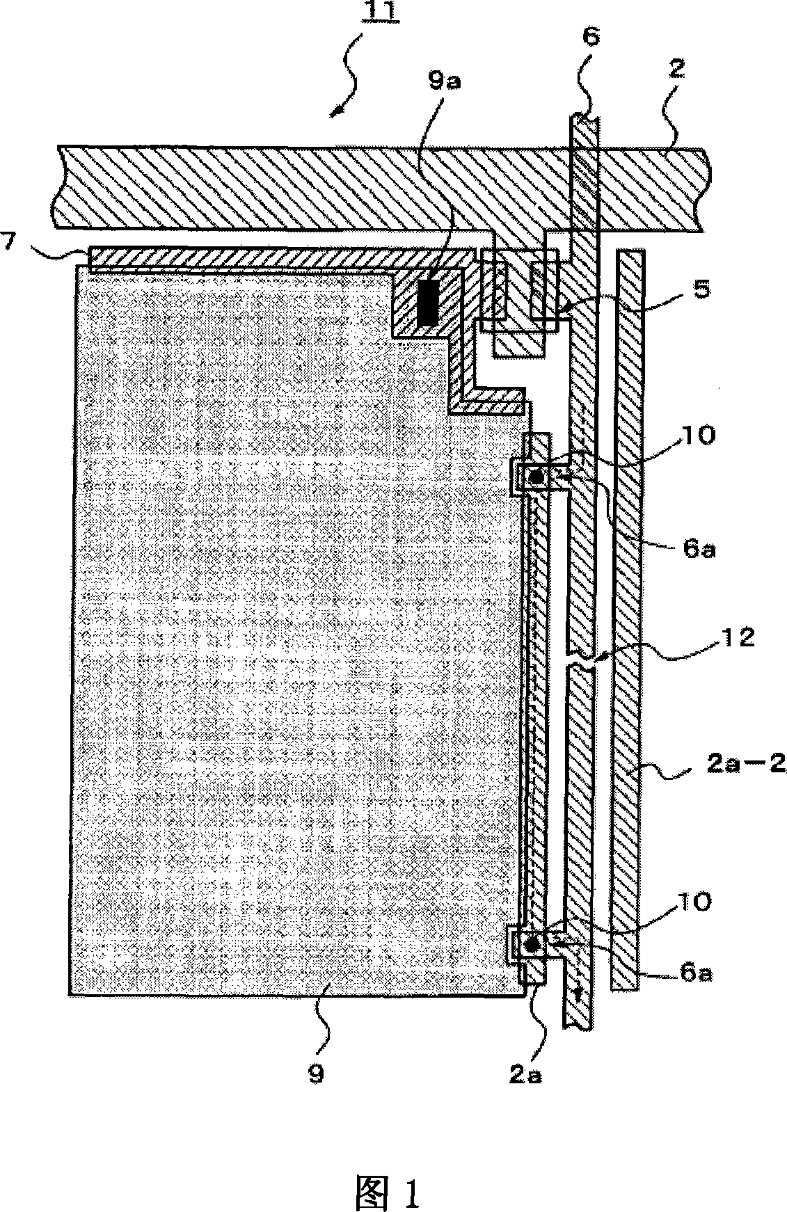
However, the above technology has its disadvantages. This technology can only repair the open circuit of the data line in the pixel interval. If the open circuit occurs at the junction of the data line and the gate scanning line or a short circuit occurs on the data line, it cannot be repaired.

Method used


Image

  • Thin film transistor array base board and its repairing method
  • Thin film transistor array base board and its repairing method
  • Thin film transistor array base board and its repairing method

Examples


Embodiment 1

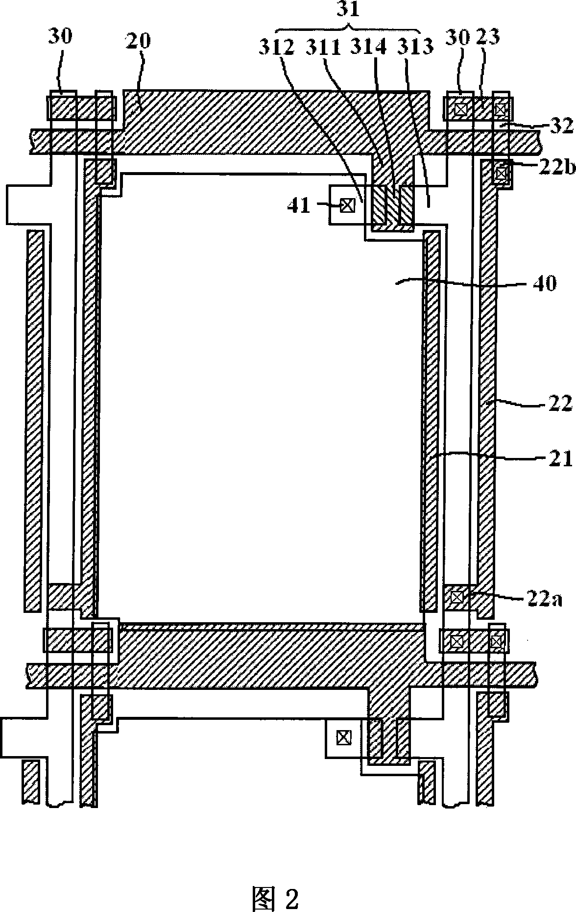
[0034] FIG. 2 is a schematic structural diagram of a TFT substrate according to Embodiment 1 of the present invention.

[0035] 2 and 5A, the thin film transistor array substrate includes a plurality of gate scanning lines 20 extending along the first direction; a plurality of data lines 30 extending along the second direction, and the gate scanning lines 20 and data lines 30 intersect to form pixels region; a thin film transistor 31 and a pixel electrode 40 are arranged in the pixel region, the thin film transistor 31 is composed of a gate 311, a source 312 and a drain 313, the gate 311 is electrically connected to the gate scanning line 20, and the drain 313 is connected to the data line 30 Electrically connected, the source electrode 312 is connected to the pixel electrode 40 through the contact hole 41, the gate electrode 311 is formed on the first metal layer, the source electrode 312 and the drain electrode are formed on the second metal layer, and there is a SiNx insulat...

Embodiment 2

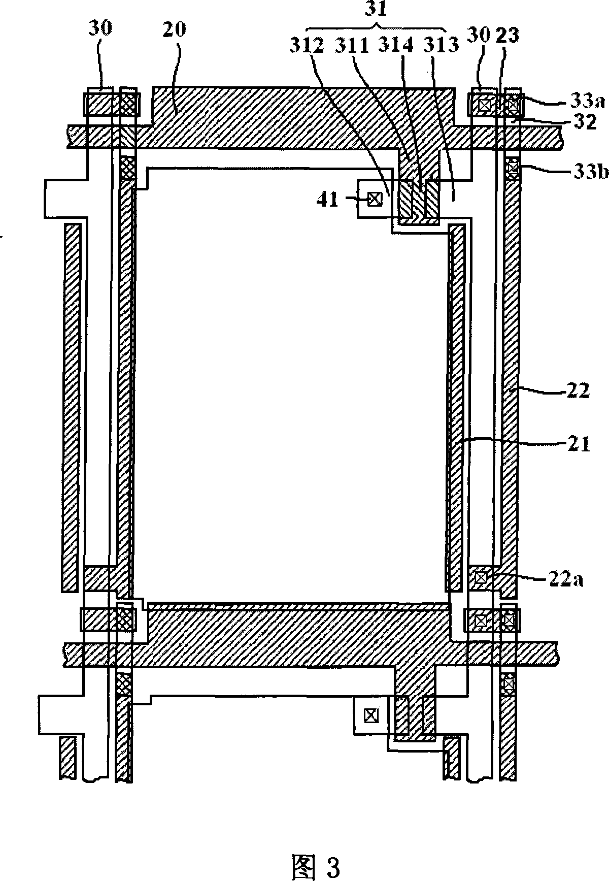
[0041] FIG. 3 is a schematic structural diagram of a TFT substrate according to Embodiment 2 of the present invention.

[0042] Referring to FIG. 3 , the difference from the structure of the thin film transistor array substrate provided in Embodiment 1 is that there is no protrusion 22b on the upper end of the outer shielding line 22 in this embodiment, and the repair line 32 is formed on the pixel electrode layer. The repair line 32 and the repair line The overlapping intersecting interlayers of the pads 23 and the outer shielding lines 22 are also respectively provided with repair pads 33 a and 33 b formed on the same metal layer (second metal layer) as the data lines 30 .

[0043] 8 is a schematic diagram of repairing the short circuit at the junction of the data line and the gate scanning line according to Embodiment 2 of the present invention; FIGS. 9A and 9B are respectively schematic cross-sectional views along the IV-IV direction of FIG. 8 before and after the repair; F...


PUM


Abstract

The basal plate of film transistor array includes following parts: multiple gated scanning wires extended along first direction; multiple data wires extended along second direction, pixel area formed between crossed gated scanning wires and data wires; thin film transistors and pixel electrodes setup inside pixel area; being distributed on two sides of data wires, inner and outer sided shading wires formed on same metal layer to the gated scanning wires; there is at least one lug at one end of the outer shading wire or data wire, and the lug makes overlap between data wire and outer sided shading wire; the other end of outer sided shading wire and one end of repairing wire crossing gated scanning wire are overlapped; the other end of the repairing wire and the repairing pad overlapped with gated scanning wire are overlapped. The invention can be in use for repairing defects of open circuit and short circuit of data wires.

Description

technical field [0001] The invention relates to an array substrate and a repair method thereof, in particular to a thin film transistor array substrate for a liquid crystal display capable of repairing open circuit or short circuit of a data line and a repair method thereof. Background technique [0002] Thin film transistor liquid crystal display (TFT-LCD) panels use thin film transistors (TFT) to control the orientation of liquid crystal molecules to control the intensity of light transmission to display images. A complete TFTLCD panel usually includes a backlight module, a polarizer, a lower substrate of a TFT array, an upper substrate of a CF (color filter), a layer of liquid crystal molecules sandwiched between the upper and lower substrates, and a driving circuit. The display area on the TFT array substrate includes a plurality of sub-pixel areas, and each sub-pixel area is generally a rectangular or other shaped area formed by the crossing of two gate scanning lines a...

Claims


Application Information

Patent Timeline
Patent Type & Authority Applications(China)
IPC IPC(8): H01L27/12H01L23/522H01L21/84H01L21/768G02F1/1362
Inventor 张锋
Owner NANJING CEC PANDA LCD TECH
Learn More