

Vibration motor of flat form
A flat vibrating motor and vibrating force technology, which is applied in the direction of electric components, casings/covers/supports, and control of mechanical energy, can solve problems such as reducing the service life of vibrating motors, achieve shock absorption, effective manufacturing process, and eliminate electricity. The effect of the interruption of the connection
- Summary
- Abstract
- Description
- Claims
- Application Information
AI Technical Summary
Problems solved by technology
Method used
Image

Examples
no. 1 approach
[0045] A coupling structure of the base part 300 and the stator part 200 according to the first embodiment of the present invention will now be described with reference to the accompanying drawings.
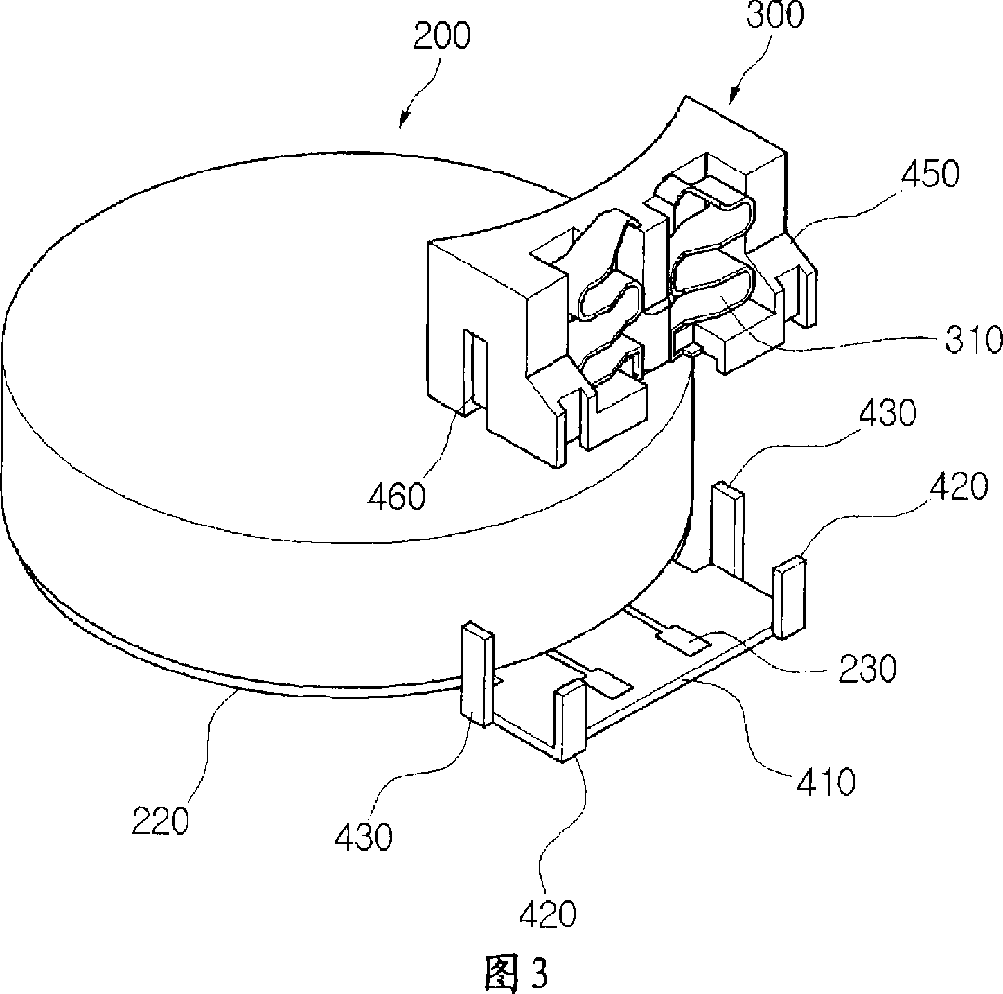
[0046] 3 is a perspective view showing a coupling structure of a base part and a stator part of a flat vibration motor according to a first embodiment of the present invention; Perspective view of the base part together.
[0047] 3 and 4, the stator part 200 has a fixing bracket 410 on which a plurality of fixing arms 420 and 430 are formed. A fixing boss 450 and a fixing groove 460 are formed on the base part 300 . A fixing bracket 410 protrudes from a side of the lower case 220 to support the bottom of the base part 300 , and fixing arms 420 and 430 are formed on edges of either side of the fixing bracket 410 .
[0048] In the flat vibration motor according to the first embodiment of the present invention, there are four fixing arms 420 and 430; however, the number thereof is...
no. 2 approach
[0060] Hereinafter, a coupling structure of a base part 300 and a stator part 200 of a flat vibration motor according to a second embodiment of the present invention will be described with reference to the accompanying drawings.
[0061] 5 is a perspective view showing a coupling structure of a base portion 300 and a stator portion 200 of a flat vibration motor according to a second embodiment of the present invention; A perspective view of the base part 300 assembled with the parts 200; FIG. 7 is a side view showing the base part 300 assembled with the stator part 200 of the flat vibration motor shown in FIG.
[0062] 5-7, the stator part 200 has a fixing bracket 410 on which a plurality of fixing arms 420' and 430 are formed. A fixing boss 450 and a fixing groove 460 are formed on the base part 300 . The fixing bracket 410 protrudes from the side of the lower case 220 to support the bottom of the base part 300, and has fixing arms 420' and 430 formed on edges of either side...
no. 3 approach
[0073] Hereinafter, a description will be given of a flat vibration motor according to a third embodiment of the present invention with reference to the accompanying drawings.
[0074] 8 is a perspective view of a base portion 300 of a flat vibration motor according to a third embodiment of the present invention; FIG. 9 shows a base connected with a stator portion 200 of a flat vibration motor according to a third embodiment of the present invention Perspective view of portion 300 .
[0075] Referring to FIG. 8, a fixing bracket 560a is formed in the fixing groove 560 obliquely inwardly. Accordingly, as shown in FIG. 9 , the second fixing arm 430 is inserted into the fixing slot 560 , and then its end 422 a is bent at an angle and engaged on the fixing frame 560 a.
[0076] The first fixing arm 420' and the second fixing boss 450 of the third embodiment can be coupled using the same structure as that of the second embodiment.
[0077] If the vibration force from the flat vib...
PUM
 Abstract
Description
Claims
Application Information