Biological safety cabinet

A technology of biological safety cabinets and microorganisms, which is applied in the direction of smoke removal, heating methods, lighting and heating equipment, etc., and can solve the problem that there is no way to determine whether the intensity of ultraviolet lamps is sufficient.

Inactive Publication Date: 2007-10-17
林向前
View PDF1 Cites 23 Cited by
  • Summary
  • Abstract
  • Description
  • Claims
  • Application Information

AI Technical Summary

Problems solved by technology

Since the early biosafety cabinets did not have a built-in UV intensity sensor, and the inspector usually did not have a UV intensity meter, there was no way to determine whether the intensity emitted by the UV lamp was sufficient

Method used


Image

  • Biological safety cabinet
  • Biological safety cabinet
  • Biological safety cabinet

Examples


Embodiment Construction

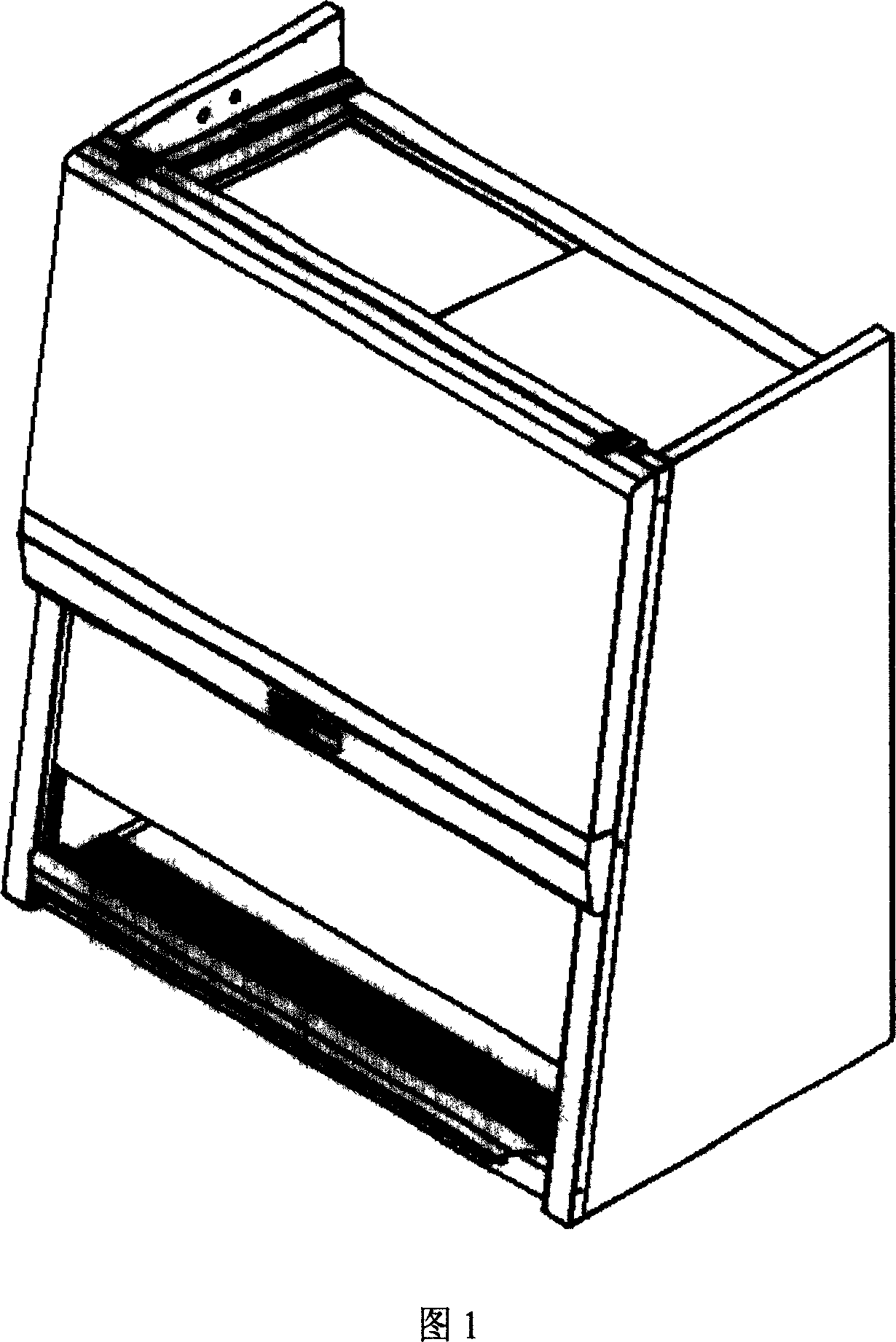
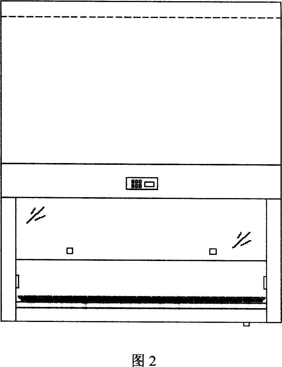
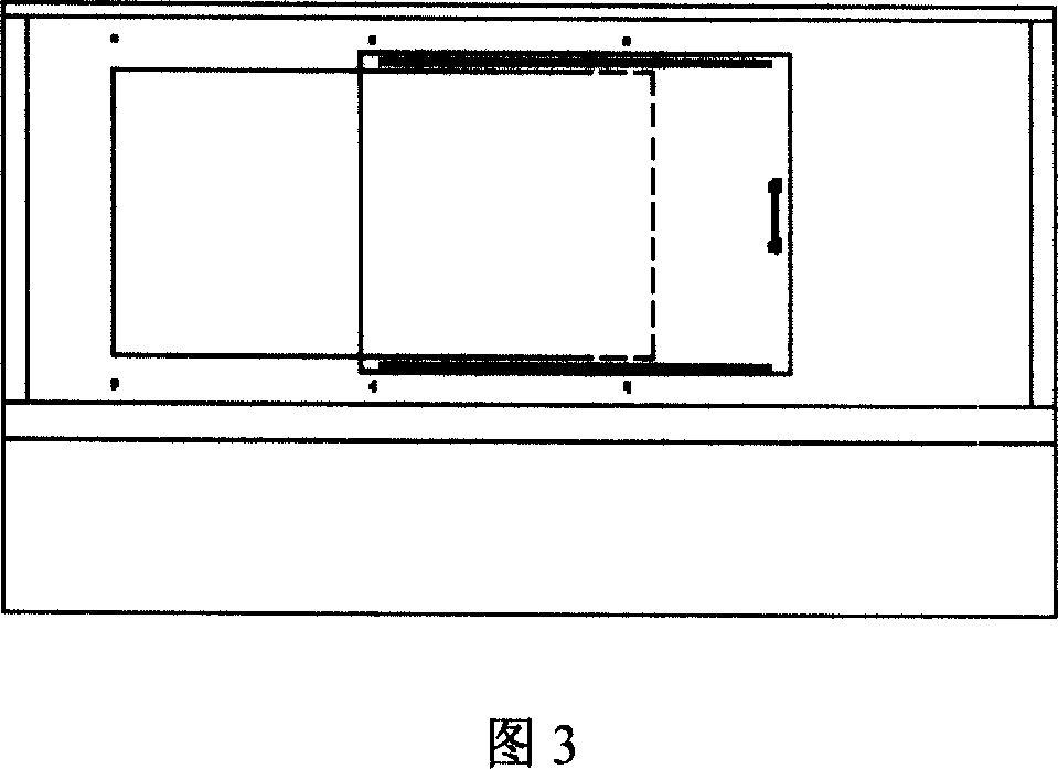
[0093] Figures 1, 2, and 3 provide external renderings of the biological safety cabinet of this invention.

[0094] Figure 4 describes the working principle of a biological safety cabinet. The biological safety cabinets discussed are open at the front and sealed on the other three sides. The operator can put his hands into the work area through the opening at the front to perform microbiological tests in the work interface area / workbench 1 . The working interface area / table 1 is sealed and formed by the inner left wall 2 , the inner rear wall 3 and the inner right wall 4 . The front portion has an opening that is regulated by a sliding front window 5 up and down. When conducting microbial experiments, the opening of the front window should be set at a specified height. In order to facilitate cleaning of the work area of ​​the safety cabinet or moving large equipment in and out of the safety cabinet, the front window can be moved upwards when no microbiological experiments a...


PUM


Abstract

The present invention provides an improved bio-safety cabinet having a microprocessor control system for the monitoring and control of the inflow, downflow and outflow of air, for creation of a performance envelope within the work chamber wherein all contaminated areas are under negative pressure or surrounded by negative pressure and the work chamber is continuously bathed in clean air, ensuring the microbiological work is protected form contamination in normal room air. Improved decontamination and other safety measures for a bio-safety cabinet are also proposed.

Description

technical field [0001] The invention relates to laboratory cleaning equipment, in particular to an improved secondary biological safety cabinet. Background technique [0002] Biological safety cabinets are laboratory clean equipment equipped with high-efficiency particulate airflow filters (hereinafter referred to as HEPA filters). These biological safety cabinets are commonly used in the analysis and research of laboratory microorganisms. Biosafety cabinets protect laboratory operators from microbial infection. Most biosafety cabinets also protect samples / products from contamination by microorganisms carried in the room air, often referred to simply as product protection. For example, US Patent No. 6368206B1 describes the performance of a Type A2 Class II biological safety cabinet. [0003] Type A2 secondary biological safety cabinet is a sealed device with a front opening. Laboratory operators can reach into the work area through the front opening for microbiological e...

Claims


Application Information

Patent Timeline
Patent Type & Authority Applications(China)
IPC IPC(8): B01L1/00B08B15/02B08B15/04F24F7/06
CPCB08B15/02B08B15/023B01L1/00B01L2300/14
Inventor 林向前
Owner 林向前
Why Eureka
Try Eureka