Bicycle five-way assembly

A bicycle and component technology, applied to bicycle accessories, bicycle racks, vehicle components, etc., can solve problems such as poor reliability, complexity, and difficult connection, and achieve the effects of easy translation, fast installation, and less labor

Active Publication Date: 2007-10-17
CAMPAGNOLO SRL
View PDF4 Cites 5 Cited by
  • Summary
  • Abstract
  • Description
  • Claims
  • Application Information

AI Technical Summary

Problems solved by technology

However, the applicant has found that the movement of the bearing relative to the half-shaft is not at all simple, since considerable force must be applied to modify the pressure coupling between the bearing and the half-shaft, generally made of steel, and because if the assembly is actually The inspection access area for the left bearing is extremely small during the nearly fully assembled installation step above
[0009] The second disadvantage is related to the difficulty of telescopically coupling the two half-axles within the axle box of the bicycle frame
The coupling between the two crank arm assemblies is typically indeed a high precision coupling, and therefore the two half-shafts are inserted into each other in the axle box, i.e. there is no visual reference possibility for the operator, it can only be achieved by trial and error, and is long and laborious
[0010] A third disadvantage has to do with the poor reliability of the bottom bracket assembly once installed inside the axle box of the bicycle frame
The inventors did find that during pedaling an axial load slightly higher than normally foreseen loads was sufficient to cause the shaft to move, and thus the crank arm relative to the midplane of the bicycle frame, thus rendering the bicycle unusable
[0011] A fourth disadvantage is related to the need to provide a positive coupling between the bearing inner ring and the shaft to lock such bearings in axial position on the shaft
In addition to the undesired stresses on the shaft itself during operation, this type of coupling does involve complications in the operation of mounting the bearings on the shaft

Method used


Image

  • Bicycle five-way assembly
  • Bicycle five-way assembly
  • Bicycle five-way assembly

Examples


Embodiment Construction

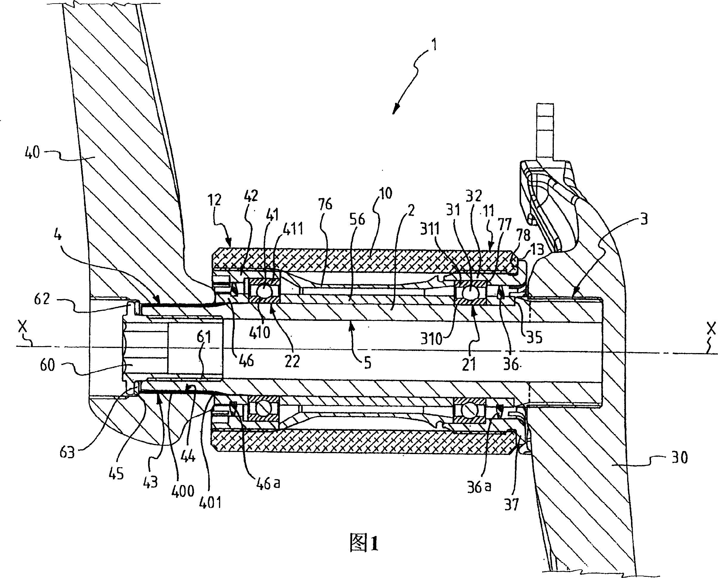
[0106] Referring to FIG. 1 , there is indicated a bicycle bottom bracket assembly according to a first embodiment of the present invention.

[0107] The assembly 1 comprises a shaft 2 having a longitudinal axis X-X extending in a predetermined direction. The shaft 2 comprises opposite end portions 3 and 4 on the right and left, respectively, with which a right crank arm 30 and a left crank arm 40 are associated, respectively.

[0108] The axle 2 is rotatably supported in an axle box 10 suitably provided in the bicycle frame by interposing right bearing 31 and left bearing 41 suitably inserted on the axle 2 between the axle 2 and the axle box 10 . The axlebox 10 is substantially cylindrical and extends along a longitudinal axis intended to coincide with the axis X-X of the axle 2 when the axle 2 is housed in the axlebox 10 .

[0109] In the particular embodiment illustrated in Figure 1, the bearings 31 and 41 are ball bearings, but other types of bearings suitable for ensuring...


PUM


Abstract

A bicycle bottom bracket assembly comprises a shaft having a longitudinal axis X-X extending along a predetermined direction and comprising a first end portion and a second end portion, a first bearing having an inner ring inserted on said shaft in a position adjacent to said first end portion and an outer ring coupled with a first adapter adapted to be associated with a first end of a housing box of the bottom bracket assembly in a bicycle frame, and a second bearing having an inner ring inserted on said shaft in a position adjacent to said second end portion and an outer ring coupled with a second adapter adapted to be associated with a second end of said housing box. The assembly further comprises first locking means of the inner rings of said first and second bearings acting on said inner rings to prevent the movement of said inner rings in both ways of said predetermined direction. In the assembly, at least one adapter comprises a first abutment surface adapted to operate in abutment against a front end surface of said housing box and a second abutment surface adapted to operate in abutment against the outer ring of at least one bearing, whereas the outer ring of the other bearing is free to move with respect to the other adapter in both ways of said predetermined direction.

Description

[technical field] [0001] The invention relates to a bicycle bottom bracket assembly. [Background technique] [0002] As is known, a bicycle bottom bracket assembly includes a shaft and two crank arms associated with opposite ends of the shaft. The shaft can be made as a separate piece from the crank arms, or it can be made as a single piece with one of the two crank arms. [0003] The components of a bicycle bottom bracket assembly, including a crank arm and an axle coupled thereto or made as a separate piece, are typically identified by the expression: crank arm assembly. [0004] The bottom bracket assembly is mounted on the bicycle by housing the axle in an axle box suitably provided within the bicycle frame. Rotation of the bottom bracket assembly relative to the axle box is achieved by inserting a pair of rolling bearings onto the shaft. Each bearing is positioned on the shaft adjacent a respective shaft portion of the crank arm. Each bearing is operatively disposed...

Claims


Application Information

Patent Timeline
IPC IPC(8): B62M1/02B62K19/30B62M1/36G05G1/30
CPCY10T74/2164B62M3/003
Inventor 朱塞佩·达尔普拉
Owner CAMPAGNOLO SRL
Why Eureka
Try Eureka