
Layer 2 forwarding method and forwarding device

A forwarding device and layer-2 forwarding technology, applied in the field of data transmission, can solve problems such as limited application scope, inability to distinguish devices, and inability to configure port isolation solutions, and achieve high reliability.

Inactive Publication Date: 2007-10-17
NEW H3C TECH CO LTD
View PDF0 Cites 18 Cited by
  • Summary
  • Abstract
  • Description
  • Claims
  • Application Information

AI Technical Summary

Problems solved by technology

[0018] 2. The scope of application is limited. For the case where the network topology of the metropolitan area network is an Ethernet ring network, the port isolation method is no longer effective, because: the uplink port of the Ethernet ring network device will not only receive the data sent by the user through the ring network. The uplink message will also receive the downlink message from the POP, where the downlink message is sent to the user port or the user-facing port of the device, while the uplink message is sent to other uplink ports, and because the uplink , the downlink packets belong to the same VLAN, the device cannot distinguish between the two packets, therefore, the port isolation scheme cannot be configured
It takes a long time for the access network equipment to recover from the discovery of a POP failure to the switch to the standby POP equipment, generally reaching the second level, which does not meet the requirements of the telecom operator for a failure time of no more than 50ms; if the access network equipment uses a similar and POP point The fast handshake fault detection method to reduce the fault recovery time will increase the requirements for access network equipment, which will undoubtedly greatly increase the cost of access network equipment
[0021] 2. High requirements for access network equipment
The access network device must have the ability to discover POP points; the access network device must also be configured with rules that only allow specific MAC address packets to pass through. In order to ensure performance, special hardware is usually required, which increases the complexity of the access network device. sex and cost

Method used


Image

  • Layer 2 forwarding method and forwarding device
  • Layer 2 forwarding method and forwarding device
  • Layer 2 forwarding method and forwarding device

Examples


Embodiment Construction

[0056] The present invention will be further described in detail below in conjunction with the accompanying drawings and specific embodiments.

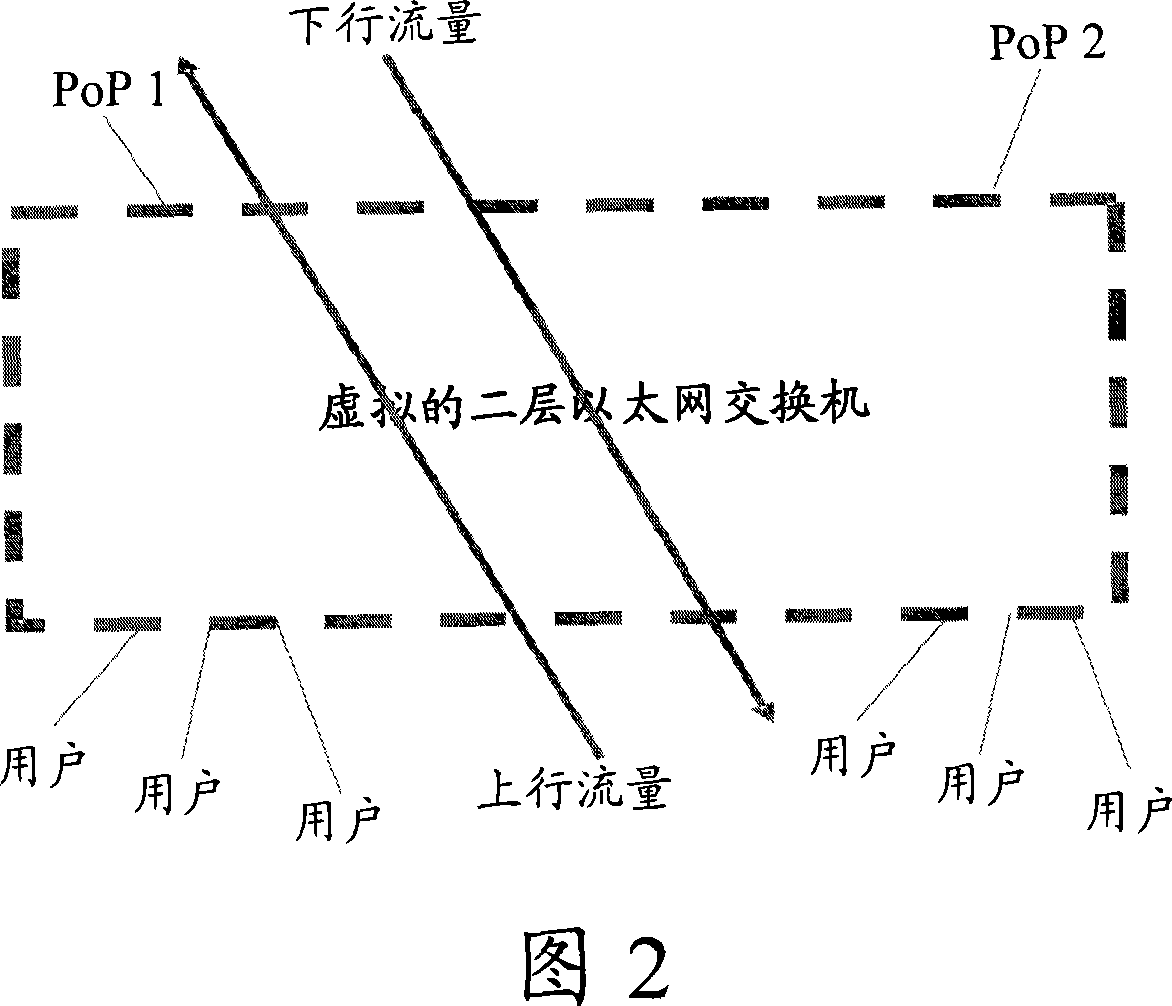
[0057] In the present invention, the upstream traffic and the downstream traffic are placed in different virtual switching planes for forwarding. Logically, it is equivalent to having two virtual Ethernet switches, one is responsible for upstream traffic forwarding, and the other is responsible for downstream traffic forwarding. As shown in Figure 4, the uplink virtual two-layer Ethernet switch is only responsible for the forwarding of uplink traffic, and the present invention refers to the virtual switching plane specially used for forwarding uplink traffic as an uplink virtual switching plane; the downlink virtual two-layer Ethernet switch is only It is responsible for the forwarding of downlink traffic. In the present invention, the virtual switching plane specially used for forwarding downlink traffic is called a downlink virtual ...


PUM


Abstract

The invention discloses a L2 forwarding method, including: pre-configure the association relation of the uplink and downlink virtual switching plane, the forwarding devices receive the broadcast sent by the user or unknown unicast packets and broadcast the packets in the uplink interface of the uplink virtual switching plane; the forwarding devices receives the packets sent by the POP point, identify the associated uplink virtual switching plane, and learn the source MAC address of the packet to the uplink virtual switching plane; later, the forwarding devices receive the known unicast packets sent by the user, search the corresponding port of the destination MAC address of the packet in the uplink virtual switching plane, and send the packets. The invention also discloses forwarding devices, including: associated module of the uplink and downlink virtual switching plane, forwarding module of the uplink packet, forwarding module of the downlink packet, and storage module of the uplink MAC forwarding table. The invention makes the forwarding devices prohibit the direct L2 intercommunication between the users without the configuration of complicated port separation scheme and MAC address of the POP points.

Description

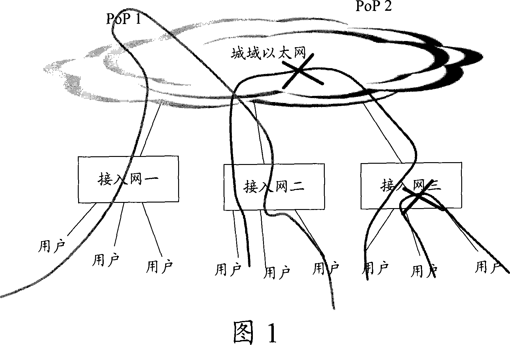
technical field [0001] The invention relates to the technical field of data transmission, in particular to a two-layer forwarding method and forwarding equipment. Background technique [0002] In the operator's network, the entire network from the access network to the operator's service provision point (PoP, Point of Presence) through the metropolitan area network may use Ethernet transmission technology, and the entire network can be regarded as a huge two-layer Ethernet network , the Layer 2 Ethernet network can be actually constructed using an Ethernet switch, or can be constructed virtually using other technologies such as: Virtual Private LAN Service (VPLS, Virtual PrivateLAN Service) technology. For security and profit considerations, it is required to prohibit direct Layer 2 intercommunication between users on the Layer 2 Ethernet network, that is, users are not allowed to communicate through the access network or the MAN. As shown in Figure 1, intercommunication be...

Claims


Application Information

Patent Timeline
IPC IPC(8): H04L12/56H04L29/02H04L45/74
Inventor 张雄张浩杰张俭锋乔剡
Owner NEW H3C TECH CO LTD
Learn More