Sealing device

A technology of sealing device and mounting part, which is applied in the direction of engine sealing, rotating parts against centrifugal force, bearings, etc., which can solve the problems of increasing sliding torque, sliding loss of auxiliary lip 55d, curling, etc., and achieve the effect of improving sealing performance

Inactive Publication Date: 2007-10-17
NOK CORP
View PDF0 Cites 11 Cited by
  • Summary
  • Abstract
  • Description
  • Claims
  • Application Information

AI Technical Summary

Problems solved by technology

It is generally believed that when grease is supplied from the inside of the bearing B to the main lips 55b, 55c, resistance to the supply of grease is generated in the direction of the auxiliary lip 55d, and the lubricity of the main lips 55b, 55c is deteriorated.
Furthermore, during assembly or action, when there is a relative positional change in the axial direction between the oil deflector ring 52 and the lip-shaped component 53, it is possible that the auxiliary lip 55d that is in close contact with the oil deflector ring 52 is curled up (the auxiliary lip 55d). lip 55d is reversed in the axial direction), it is hoped that this can be improved
[0006] In this regard, an improvement has been proposed in the past. As shown in FIG. 3, the auxiliary lip 55d does not come into contact with the oil deflector ring 52, but directly slides against the outer peripheral surface 21a of the bearing inner ring 21 (see Patent Document 1 2 ), according to the sealing device 51 in FIG. 3 , since the auxiliary lip 55d slides relative to the bearing inner ring 21 which is not intended to slide in close contact with it, the sliding moment is increased, and the auxiliary lip 55d is prone to sliding loss. The problem

Method used


Image

  • Sealing device
  • Sealing device
  • Sealing device

Examples


Embodiment

[0056] Embodiments of the present invention will be described below with reference to the drawings.

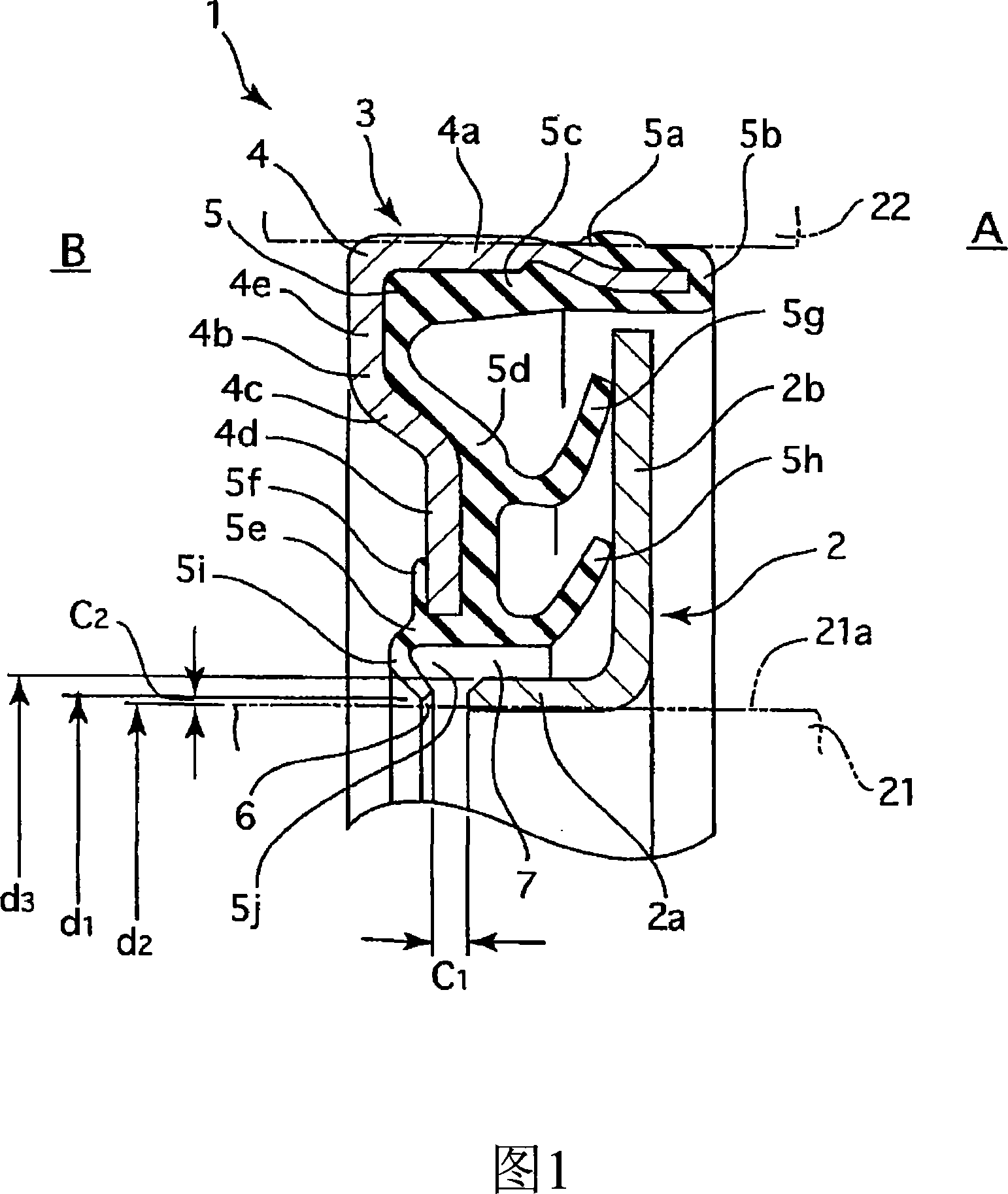
[0057] Fig. 1 shows a cross-sectional view of main components of a sealing device 1 according to an embodiment of the present invention. The sealing device 1 described in this embodiment is used as a wheel hub bearing seal in the field of automobiles, and has the following structure.

[0058] That is, the sealing device (packing seal) 1 has an oil slinger 2 and a lip member 3, the former being mounted on and rotating with a bearing inner ring 21 as one of two parts which rotate relatively, And the latter is mounted on the bearing outer ring 22, which is the other of the two parts, which is tightly attached to the oil deflector ring 2 and can slide freely. The spherical body (rotating body, not shown in the figure) of the bearing is on the left side of the figure of the sealing device 1, so the right side in the figure is the bearing exterior A, and the left side is the bearin...


PUM


Abstract

A pack type sealing device (1), comprising a slinger (2) and a lip member (3), wherein a torque due to the slidable movement of an auxiliary lip (5i) is prevented from increasing, the auxiliary lip (5i) is prevented from becoming a large lubricating resistance against main lips (5g) and (5h), a peeling-off trouble on the auxiliary lip (5i) is prevented from occurring, and the auxiliary lip (5i) is prevented from being worn due to slidable movement. The sealing device (1) is formed by combining the slinger (2) installed on one member (21) of two members rotating relative to each other with the lip member (3) installed on the other member (22). The slinger (2) comprises a mounting part (2a) and a flat surface part (2b) which are formed integrally with each other, and the lip member (3) comprises the main lips (5g) and (5h) fitted to the end face of the flat surface part (2b) of the slinger (2). The auxiliary lip (5i) of labyrinth structure radially facing the peripheral surface (21a) of the one member (21) is formed on the inside of the main lips (5g) and (5h) at a position axially displaced from the mounting part (2a) of the slinger (2).

Description

technical field [0001] The invention relates to a sealing device related to sealing technology. The sealing device of the present invention is used, for example, as a sealing device for hub bearings in the related fields of automobiles, or as a muddy water sealing device in agricultural machinery, construction machinery, general machinery, and the like. Background technique [0002] In the past, as a sealing device for hub bearings in the automobile-related field, a packing type sealing device (packing seal) 51 as shown in FIG. An oil deflector 52 that rotates together with the bearing inner ring 21 and a lip member 53 that is mounted on the bearing outer ring 22 and is in close contact with the oil deflector 52 and is slidable is composed of a combination (see FIG. 5 of Patent Document 1). [0003] The oil retaining ring 52 is made of a metal material, and on one axial end (right end in the figure) of the cylindrical mounting portion 52a, an annular planar portion 52b is i...

Claims


Application Information

Patent Timeline
Patent Type & Authority Applications(China)
IPC IPC(8): F16J15/447F16C33/78F16C33/80F16J15/32F16J15/3232F16J15/3248
CPCF16C33/7879F16J15/3264F16C2240/40F16C2240/70F16C33/78F16C33/80F16J15/32F16J15/447
Inventor 松井宏树神前刚
Owner NOK CORP
Why Eureka
Try Eureka