Thumb mechanism for under-driven adaptive prosthetic hand

An adaptive and underactuated technology, applied in artificial arms and other directions, can solve the problems of lack of realistic human hands, the placement of thumb and thumb, and the lack of anthropomorphic movement flexibility, to achieve improved flexibility and reliability, and a realistic appearance. , the effect of freedom of movement

Inactive Publication Date: 2007-10-24
HARBIN INST OF TECH
View PDF1 Cites 23 Cited by
  • Summary
  • Abstract
  • Description
  • Claims
  • Application Information

AI Technical Summary

Problems solved by technology

[0003] The purpose of the present invention is to provide a thumb mechanism of an under-actuated self-adaptive prosthetic hand, which can solve the problem that the thumb mechanism of the existing under-actuated self-adaptive prosthetic hand has not achieved the number of knuckles of the thumb, the placement position of the thumb and the flexibility of movement. Completely humanoid, there is no problem of realistic human hands

Method used


Image

  • Thumb mechanism for under-driven adaptive prosthetic hand
  • Thumb mechanism for under-driven adaptive prosthetic hand
  • Thumb mechanism for under-driven adaptive prosthetic hand

Examples


specific Embodiment approach 1

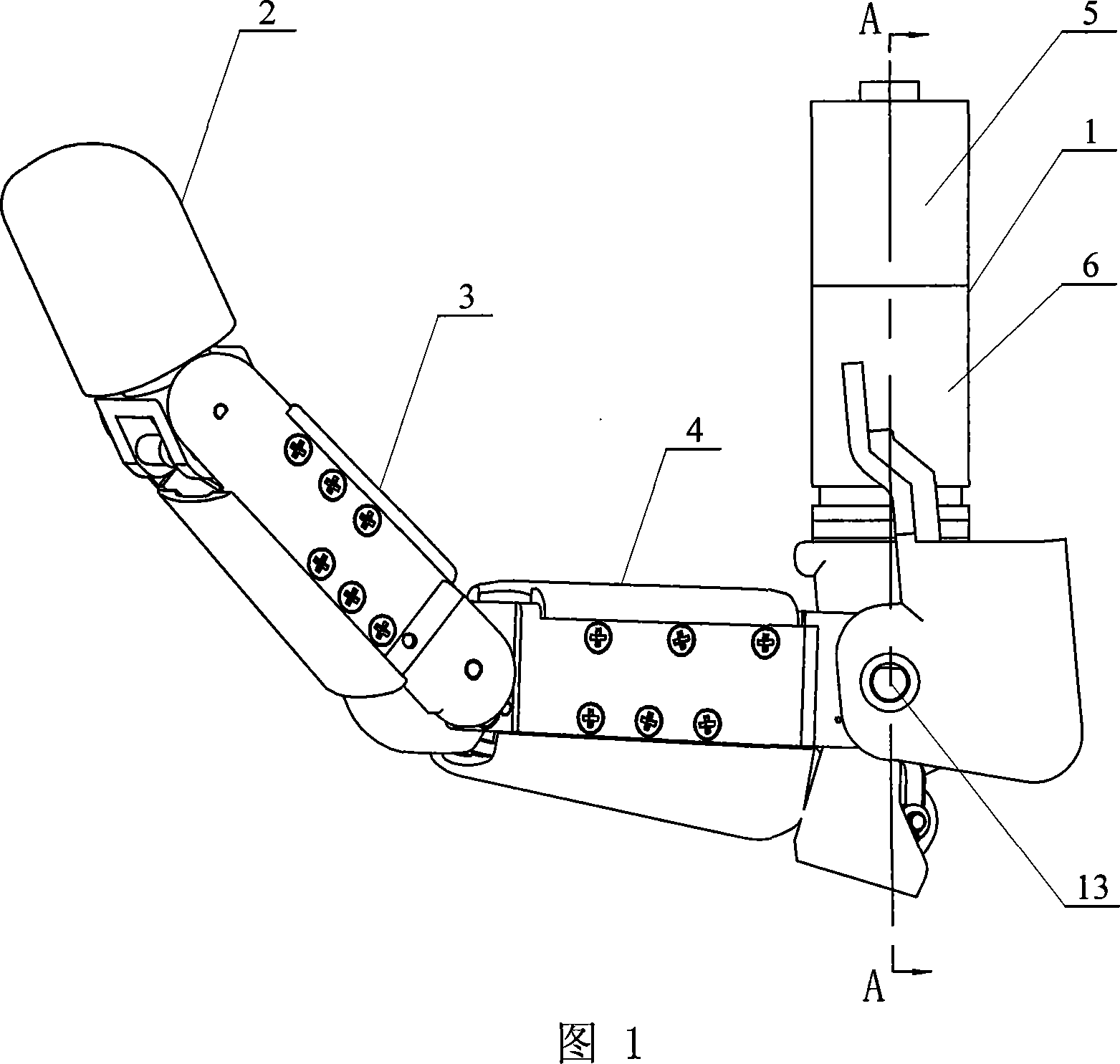
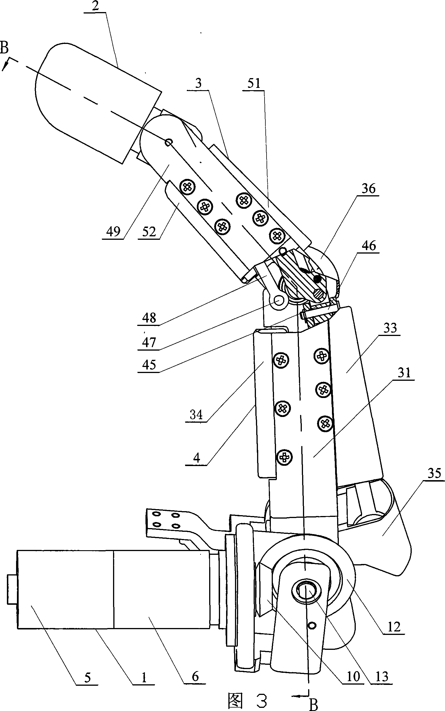
[0007] Specific embodiment one: this embodiment is described in conjunction with Fig. 1, and this embodiment is made up of transmission mechanism 1, far knuckle 2, middle knuckle 3 and proximal knuckle 4; The rear end of described transmission mechanism 1 and proximal knuckle 4 rotates Connection; the front end of the proximal knuckle 4 is rotationally connected with the rear end of the middle knuckle 3, and the front end of the middle knuckle 3 is rotationally connected with the rear end of the distal knuckle 2.

specific Embodiment approach 2

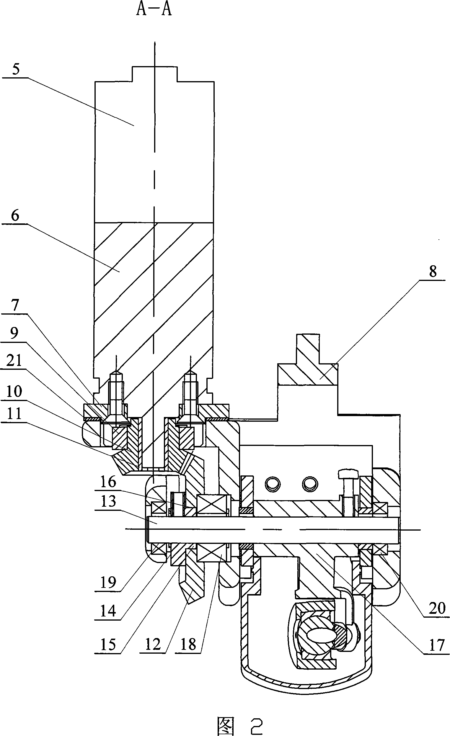
[0008] Specific embodiment two: This embodiment is described in conjunction with Fig. 1 and Fig. 2, and the transmission mechanism 1 of this embodiment is composed of a stepper motor 5, a reducer 6, a motor base 7, a thumb base 8, a motor bearing 9, and a small bevel gear 10 , a motor sleeve 11, a large bevel gear 12, a base joint shaft 13, a gear retainer 14, a sensor 17, a thrust bearing 18, and a first bearing 20; the output shaft of the stepping motor 5 and the input of the reducer 6 The shaft transmission is connected, the reducer 6 is fixedly connected to the motor base 7, the motor base 7 is fixedly connected to the thumb base 8, the motor base 7 is equipped with a motor bearing 9, and the small bevel gear 10 is mounted on the reducer 6 through a motor sleeve 11. The small bevel gear 10 meshes with the large bevel gear 12 on the output shaft, the large bevel gear 12 is installed on the base joint shaft 13, and the two ends of the base joint shaft 13 are installed in the ...

specific Embodiment approach 3

[0009] Specific embodiment three: This embodiment is described in conjunction with Fig. 2. The difference between this embodiment and specific embodiment two is: the transmission mechanism 1 of this embodiment is also increased with a motor adjustment gasket 21; the motor adjustment gasket 21 is installed Between the motor base 7 and the thumb base 8. Such setting is used to adjust the meshing gap between the large bevel gear 12 and the small bevel gear 10 .


PUM


Abstract

The invention discloses a thumb device for artificial hand. The driving device (1) is in rotary connection with the back part of near knuckle (4), the front part of near knuckle is in rotary connection with back part of middle knuckle (3), and the front end of middle knuckle is in rotary connection with the back part of far knuckle (2). The middle knuckle and near knuckle imitate deficient activation motion of real hand driven by middle knuckle shaft disk, the middle knuckle and far knuckle imitate coupling motion of real hand driven by coupling rod; and the knuckle number of thumb is imitative to that of real hand. The invention is characterized by simple structure, real-like appearance and flexible motion of each knuckle.

Description

technical field [0001] The invention relates to a thumb mechanism of an artificial hand. Background technique [0002] At present, the thumbs of most of the prosthetic hands installed by the disabled can only move in one direction, and it is difficult to imitate the spatial movement of the human thumb, so that the position of the thumb on the palm, the appearance of the thumb and the human hand have great differences. difference. Also for this reason, many disabled people who need prosthetic hands are reluctant to use prosthetic hands. According to the survey, more than half of the disabled people pay more attention to the realism of the appearance of the prosthetic hand, which can be said to be a big bottleneck in the design of the current prosthetic hand. The patent application publication number is CN 1803413A, and the patent application date of publication is July 19, 2006, which discloses a "thumb mechanism for underactuated self-adaptive prosthetic hand". The number...

Claims


Application Information

Patent Timeline
Patent Type & Authority Applications(China)
IPC IPC(8): A61F2/54
Inventor 姜力刘宏俞昌东史士财黄海
Owner HARBIN INST OF TECH
Why Eureka
Try Eureka