Focal plane shutter for digital cameras

A technology of focal plane shutter and digital camera, which is applied in the field of focal plane shutter, and can solve the problems that the hook part cannot return to the original shape, the engagement part and the engaged part cannot be well engaged, and deflection occurs.

Active Publication Date: 2007-10-31
COPAL CO LTD
View PDF3 Cites 20 Cited by
  • Summary
  • Abstract
  • Description
  • Claims
  • Application Information

AI Technical Summary

Problems solved by technology

In particular, when the setting member returns to the initial position, since the restrained portion of the first drive member for the front blade is in pressure contact with the restraining portion of the restraining member due to the biasing force of the setting spring, the hook portion may come into contact with the first driving member for the front blade. A deflection occurs before the restraint of the drivi...

Method used


Image

  • Focal plane shutter for digital cameras
  • Focal plane shutter for digital cameras
  • Focal plane shutter for digital cameras

Examples


Embodiment 1

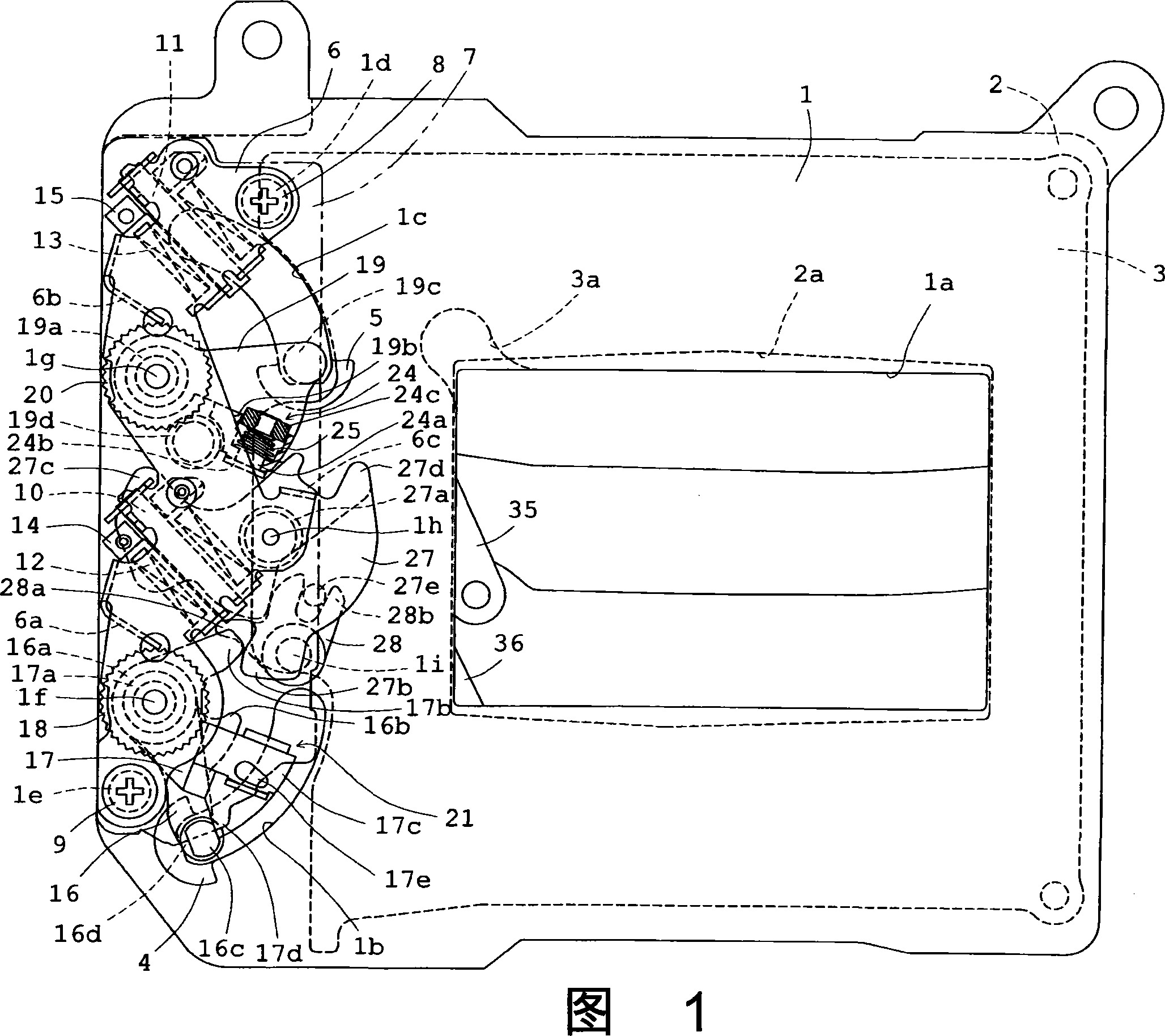
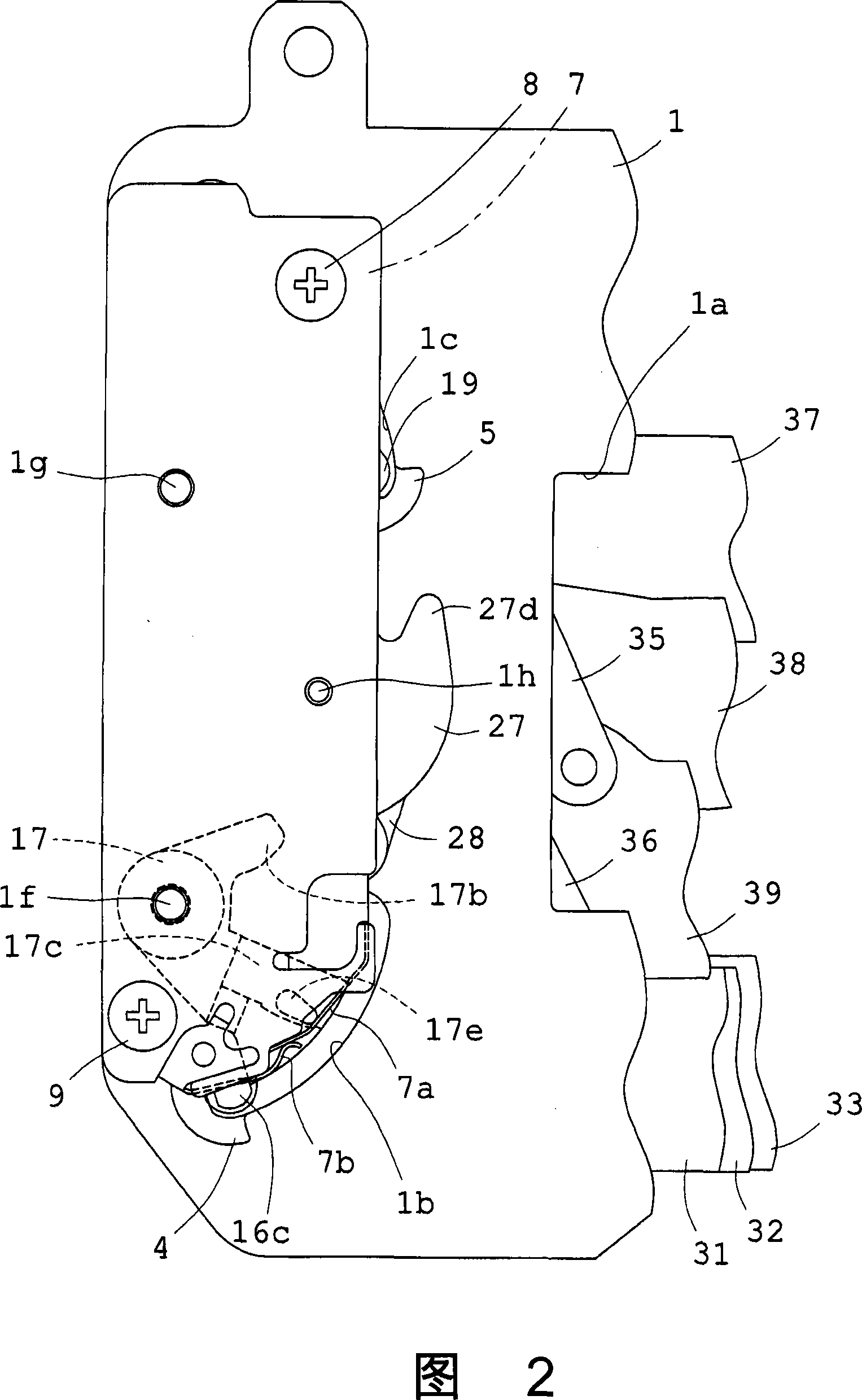
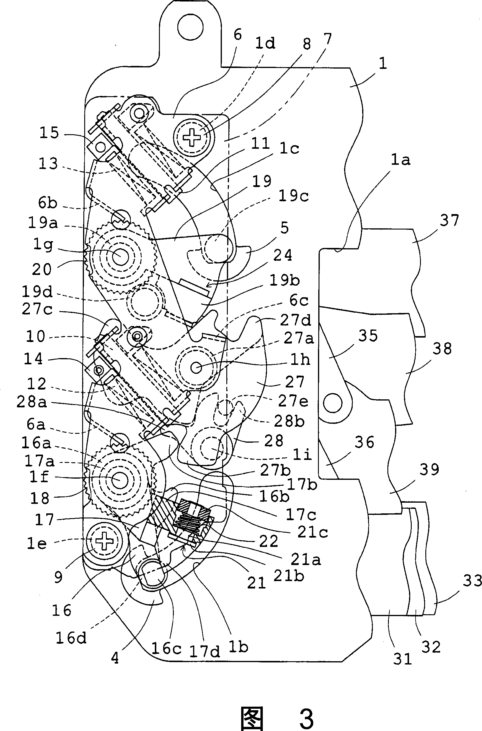
[0034] Fig. 1 is a plan view from the side of the subject in the state of being installed in the camera, and the outline of the printed circuit board is indicated by a two-dot dash line to easily show the state of the constituent members immediately after the exposure operation . FIG. 2 is an enlarged plan view of a part of FIG. 1 , and is shown for understanding a printed circuit board and a switch mechanism mounted thereon. FIG. 3 is a partially enlarged plan view similar to FIG. 1 . Fig. 4 is a cross-sectional view, seen from the right side of Fig. 2 and Fig. 3 , showing the overlapping relationship of constituent members for easy understanding. FIGS. 5 to 11 are plan views showing only main components necessary for explaining the operation of the components shown in FIG. 3 . FIG. 5 is the same as FIG. 3 and shows the state immediately after the exposure operation is completed. FIG. 7 shows the state of the setting operation performed from the state of FIG. 6 . Fig. 8 s...

Embodiment 2

[0074] Embodiment 2 will be described below. Like FIG. 3 , FIG. 13 is a plan view showing the state immediately after the exposure operation, but the mounting portion 17c of the second driving member 17 for the front blade is not cut and shown. In addition, FIG. 14 is a cross-sectional view seen from the right side of FIG. 13 to make the overlapping relationship of the constituent members easy to understand. In addition, in the structure shown in FIG. 2 used in the description of Example 1, the suppression member 28 is removed and used for description of this Example. In addition, the above-mentioned FIG. 12 used in the description of the operation of the first embodiment is also used in the description of the operation of the present embodiment. In addition, most of the constituent members of the present embodiment are the same as those of the first embodiment described above. Therefore, in FIG. 13 and FIG. 14 , the same members and the same parts as in the first embodiment...


PUM


Abstract

A shutter for digital cameras includes a first driving member for a front blade and a second driving member for the front blade, mounted to the same shank; arms for the front blade on which a set spring is hooked; and a set member for restraining the first driving member for the front blade in the proximity of the position where the exposure operation is completed, at a set position by rotating a restraining member, and actuating the first driving member for the first blade to the starting position of the exposure operation in the restoration to the initial position immediately after the release. When the second driving member for the front blade is failure to actuate because of the failure on the circuit, the said set member wound not carried out the next setting operation.

Description

technical field [0001] The invention relates to a focal plane shutter for a digital camera. Background technique [0002] Among the focal plane shutters for digital cameras, the focal plane shutter of the following form is known: the same as the focal plane shutter for silver salt film cameras, including two shutter blades, the front blade and the rear blade, when shooting, the front blade and the rear blade The trailing blades move sequentially in the same direction, and continuously expose the imaging surface of an imaging device such as a CCD from one to the other using the slit formed between the two. In addition, these front blades and rear blades are connected to the driving member for the front blade and the driving member for the rear blade. Immediately after the camera is released, the energization to the electromagnet for the front blade and the electromagnet for the rear blade is sequentially cut off, and these driving members are activated. The urging force of e...

Claims


Application Information

Patent Timeline
IPC IPC(8): G03B9/36G03B9/08
Inventor 吉田克信井上信义
Owner COPAL CO LTD
Why Eureka
Try Eureka