Optical mouse with shading device and operation method thereof

A shielding device and optical technology are applied in the field of shielding structures of optical mice, which can solve problems such as safety concerns, and achieve the effects of reducing production costs and avoiding arbitrary movement.

Inactive Publication Date: 2007-10-31
DEXIN
View PDF0 Cites 7 Cited by
  • Summary
  • Abstract
  • Description
  • Claims
  • Application Information

AI Technical Summary

Problems solved by technology

At present, the existing laser and optical mouse do not have a simple shielding mechanism to turn off the source of the light source, which leads to safety concerns when using a laser or optical mouse

Method used


Image

  • Optical mouse with shading device and operation method thereof
  • Optical mouse with shading device and operation method thereof
  • Optical mouse with shading device and operation method thereof

Examples


Embodiment Construction

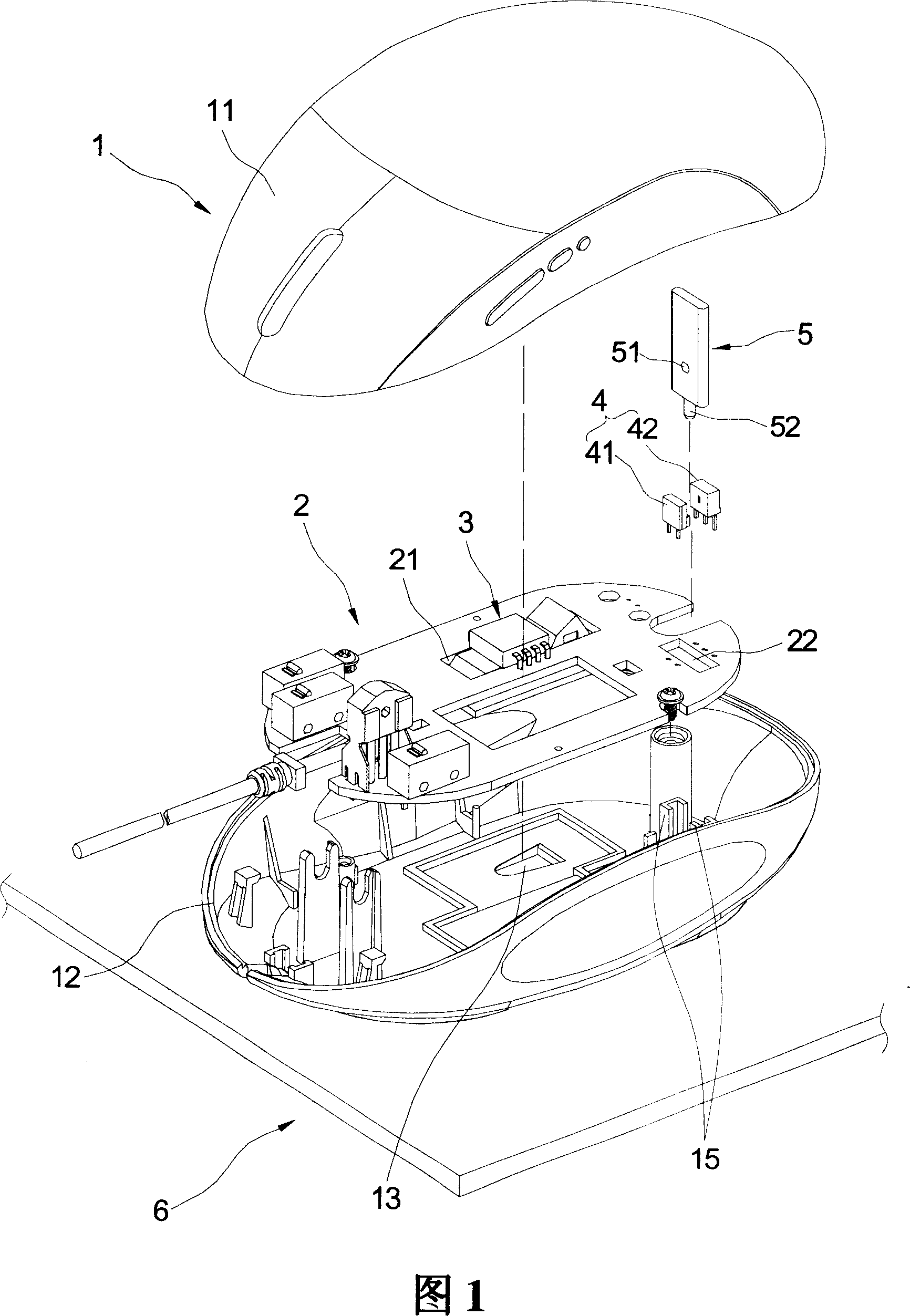
[0058] Please refer to FIG. 1 , which is an exploded perspective view of the optical mouse of the present invention. First of all, in the embodiment of the present invention, since some components of the mouse such as buttons, scroll wheels, and key switches are existing technologies, the present invention will not be described again. Meanwhile, the mouse of the present invention is not limited to a wireless mouse or a cable mouse, and the cable mouse is taken as an example in the drawings of the present invention.

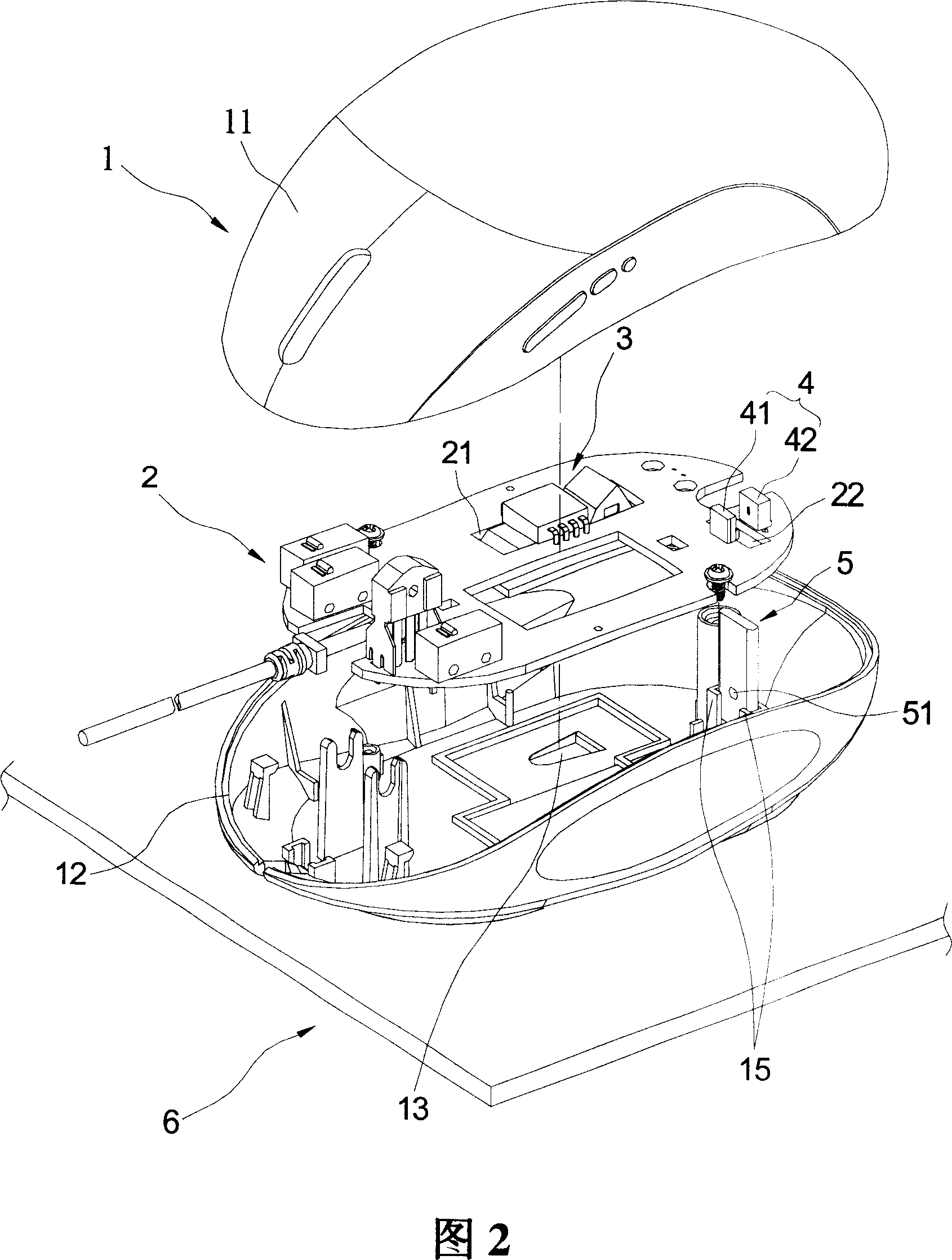
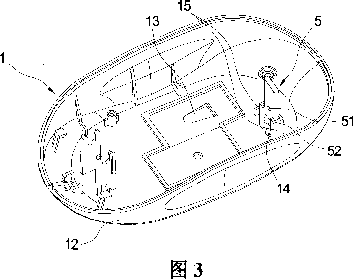
[0059] Please refer to FIG. 1 to FIG. 3 again, the present invention provides an optical mouse with a shielding device, which can be operated on a working surface 6, such as a desktop or a mouse pad. The mouse at least includes a casing 1 , a circuit board 2 , a sensor light source device 3 , an infrared control device 4 and a shielding part 5 .

[0060] Wherein, the housing 1 is roughly in the shape of an arc, and can be ergonomically designed to meet the comfor...


PUM


Abstract

This invention relates to one optical mouse cursor with one shield deice on one work plane, which comprises the following parts: shell; circuit board inside shell; sensor light source device connected to circuit board; infrared control device connected to circuit board; one shield part set inside shell to shield the infrared control device optical signals.

Description

technical field [0001] The invention relates to an optical mouse safety device, in particular to a shielding structure for the optical mouse, which can automatically block the optical signal of the infrared control device of the optical mouse when the optical mouse leaves the working plane. Background technique [0002] With the advancement of computer software and the popularization of graphical user interfaces, the mouse has been widely used in computer user interfaces. And the main board connection interface specifications of the mouse and the computer have connectors of RS-232, PS2, USB specifications, or a wireless mouse. The conventional working principle of the mouse can be divided into mechanical type and optical type. The mechanical mouse uses the belly rolling ball to drive the coordinate roller, but because the rolling ball is used to drive the coordinate roller, after long-term use, dust is easy to accumulate. On the coordinate roller, the sensitivity of the mou...

Claims


Application Information

Patent Timeline
Patent Type & Authority Applications(China)
IPC IPC(8): G06F3/033G06F3/0354
Inventor 张原荣
Owner DEXIN
Why Eureka
Try Eureka