
Solid electrolytic capacitor assembly

一种固体电解电容、电容组件的技术,应用在固体电解电容器、电解电容器、电容器零部件等方向,能够解决电容器损坏、瓶颈过热等问题

Active Publication Date: 2007-10-31
AVX CORP
View PDF14 Cites 7 Cited by
  • Summary
  • Abstract
  • Description
  • Claims
  • Application Information

AI Technical Summary

Problems solved by technology

During use, these bottlenecks tend to overheat as current passes through the anode, causing damage to the capacitor

Method used


Image

  • Solid electrolytic capacitor assembly
  • Solid electrolytic capacitor assembly
  • Solid electrolytic capacitor assembly

Examples


example 1

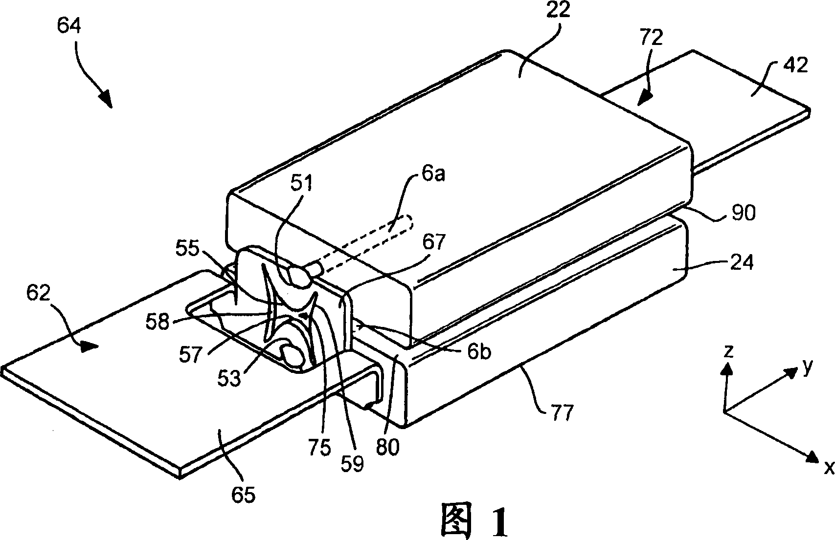
[0056] Two tantalum capacitor elements are used to form a capacitor assembly as previously described and shown in FIGS. 1 to 8 . The tantalum powder used to form each capacitive element had a charge to mass ratio of 150,000 μF*V / g (available from H.C. Starck Company). The tantalum powder was compressed using known techniques such that the resulting pellets had a length of approximately 5.35 mm, a width of 3.7 mm and a thickness of 0.75 mm. The pellets were sintered at 1245°C for 10 minutes. The pellets were anodized at 15 volts, impregnated with manganese dioxide, and coated with graphite and silver layers in the manner previously described. Each individual tantalum portion has a capacitance of approximately 500 μF. These sections were then connected in parallel with the common anode and cathode terminals as previously described so that the final capacitance of the assembly was about 1000 μF and the nominal voltage was 4 volts. These capacitive assemblies were packaged in a...

example 2

[0063] Two niobium oxide ("NbO") capacitive elements were used to construct the capacitive assembly as previously described and illustrated in FIGS. 1-8. The niobium oxide powder used to form these capacitive elements had a charge to mass ratio of 80,000 μF*V / g (available from H.C. Starck Company). The niobium oxide powder was pressed using known techniques so that the resulting pellets had a length of approximately 5.35 mm, a width of 3.7 mm and a thickness of 0.75 mm. The pellets were sintered at 1380°C for 10 minutes. The pellets were anodized at 27 volts, impregnated with manganese dioxide, and coated with graphite and silver layers in the manner previously described. Each individual niobium oxide portion has a capacitance of about 110 μF. These sections were then connected in parallel with the common anode and cathode terminals as previously described so that the final capacitance of the assembly was about 220 μF and the nominal voltage was 4 volts. These capacitive as...

example 3

[0065] The capacitor was constructed as described in Example 2, except that the anode was slotted and a forming voltage of 21 volts was used. A slotted anode has two parallel grooves that run along the entire length of the anode on each side (-x direction). Each groove has a width of 0.4 mm and a thickness of 0.25 mm. The slotted anode had a length of 5.35 mm, a width of 3.7 mm and a thickness of 0.76 mm.


PUM


Abstract

An integrated capacitor assembly that offers improved performance characteristics in a convenient and space-saving package is provided. More specifically, the capacitor assembly contains a first solid electrolytic capacitor element and second solid electrolytic capacitor element positioned adjacent to the first solid electrolytic capacitor element. The first and second solid electrolytic capacitor elements each contain an anode formed from a valve metal composition having a specific charge of about 70,000 muF*V / g or more, the anode having a thickness of from about 0.1 to about 4 millimeters. A thermally conductive material is positioned between the first and second solid electrolytic capacitor elements and electrically connected thereto. The thermally conductive material has a coefficient of thermal conductivity of about 100 W / m-K or more at a temperature of 20 DEG C. A case encapsulates the first and second solid electrolytic capacitor elements.

Description

[0001] Cross References to Related Applications [0002] This application claims priority to US Provisional Patent Application Serial No. 60 / 795,970, filed April 28, 2006, which is hereby incorporated by reference in its entirety. Background technique [0003] A wide variety of modern technology applications creates a need for efficient electronic devices and integrated circuits for use in these applications. Capacitors are fundamental devices used for filtering, decoupling, bypassing, and other aspects of these modern applications, which can include wireless communications, high-speed processing, networking, circuit switching, and many others. The dramatic increase in the speed and packing density of integrated circuits calls for advances in decapacitive component technology. Performance characteristics become increasingly important when bulk decoupling capacitors are subjected to the high frequencies found in many of today's applications. Since capacitors are fundamental t...

Claims


Application Information

Patent Timeline
Patent Type & Authority Applications(China)
IPC IPC(8): H01G9/26H01G9/15H01G9/04H01G2/08
CPCH01G9/26H01G9/012H01G9/15H01G9/042H01G9/14H01G9/025H01G9/048
Inventor L·马雷克J·托马斯科S·泽德尼切克
Owner AVX CORP
Features
  • Generate Ideas
  • Intellectual Property
  • Life Sciences
  • Materials
  • Tech Scout
  • Unparalleled Data Quality
  • Higher Quality Content
  • 60% Fewer Hallucinations
Learn More