Diaphragm chuck

A diaphragm type and chuck technology, applied in chucks, manufacturing tools, mechanical equipment, etc., can solve problems such as complex production and inaccurate processing of workpieces

Active Publication Date: 2007-11-07
SMW AUTOBLOK SPANNSYST GMBH
View PDF0 Cites 8 Cited by
  • Summary
  • Abstract
  • Description
  • Claims
  • Application Information

AI Technical Summary

Problems solved by technology

However, in order to ensure that a close contact with both reference surfaces is always obtained, the individual components of the diaphragm chuck must be produced with high precision
This makes production very complex, however, bending and / or tilting moments during tightening of the quick clamping device can disengage the jaws or collets from the contact surface on the diaphragm
This in turn causes inaccuracies during machining of the workpiece

Method used


Image

  • Diaphragm chuck
  • Diaphragm chuck
  • Diaphragm chuck

Examples


Embodiment Construction

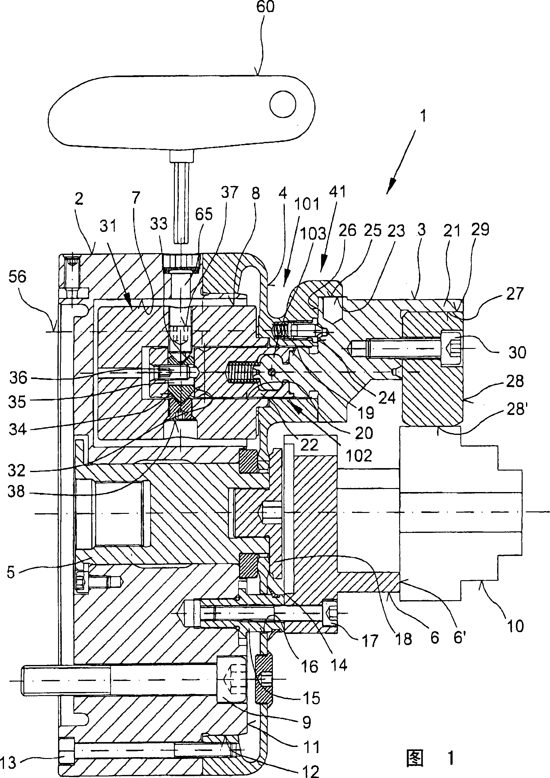
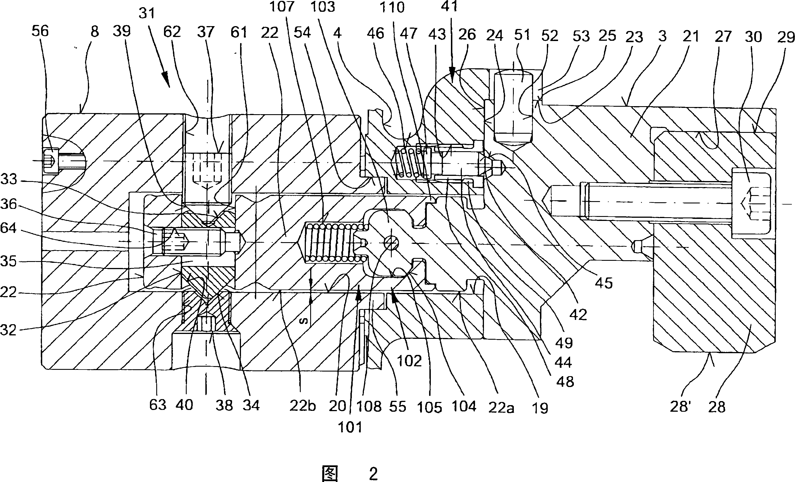
[0022] Diaphragm chuck shown in Fig. 1 is denoted by numeral 1, it is specially used for clamping high-quality workpiece 10, such as a gear, and is mainly composed of jaws 3 inserted into chuck body 2, and jaws 3 function On the workpiece 10 , the workpiece 10 is in driving connection with a deformable membrane 4 made of metallic material on a front face 12 attached by bolts 13 to recesses 12 in the exterior of the chuck body 2 .

[0023] For actuating the diaphragm 4 a centrally arranged actuator 5 is provided, into which an adjustable pull rod is screwed via a servo (not shown) on the end face remote from the jaw 3 . At the other end of the actuator 5 the diaphragm 4 with the crown collar 14 is clamped by the disc 18 .

[0024] In addition, counterweights 8 are inserted into the grooves 7 penetrating into the chuck body 2 facing the jaws 3, and these counterweights 8 counteract the centrifugal force generated by the jaws 3 when the diaphragm chuck 1 rotates , and the jaw 3 ...


PUM


Abstract

In an diaphragm chuck ( 1 ) with clamping jaws ( 3 ) inserted in its chuck body ( 2 ) that are in a driven connection with a diaphragm ( 4 ) that can be deformed by an axially adjustable actuator ( 5 ) and is provided with clamping jaws ( 3 ) with contact pieces ( 22 ), in which counterweights ( 8 ) assigned to the clamping jaws ( 3 ) are inserted into recesses ( 7 ) of the chuck body ( 2 ) and the clamping jaws ( 3 ) can be clamped against the diaphragm ( 4 ) by means of quick-clamping devices ( 31 ) engaging in the contact pieces ( 22 ), the clamping jaws ( 3 ) being supported directly against a first reference surface ( 23 ) running axially in parallel to the chuck body ( 2 ) in the clamping position and against a second reference surface ( 24 ) running at right angles to the first reference surface ( 23 ) and worked onto the diaphragm ( 4 ), the contact pieces ( 22 ) are each provided with an intermediate element ( 101 ), for example in the form of a ball joint ( 102 ), in the area between the clamping jaws ( 3 ) and the quick-clamping devices ( 31 ) by means of which the flexural moments and/or rotational torques created by the quick-clamping device ( 31 ) can be eliminated and it is possible to transmit exclusively axially vectored tensile forces onto the clamping jaws ( 3 ).

Description

technical field [0001] The invention relates to a diaphragm chuck as defined in the pre-qualified features of claim 1 . Background technique [0002] A diaphragm chuck of this type is described in European Patent Application No. 05018464.7. Practice has proved that this chuck is effective in practice. However, in order to ensure that an intimate contact with both reference surfaces is always obtained, the individual components of the diaphragm chuck must be produced with a high degree of precision. This makes production very complex, however, bending and / or tilting moments occurring during tightening of the quick clamping device can disengage the jaws or collets from the contact surface on the membrane. This in turn causes inaccuracies during machining of the workpiece. Contents of the invention [0003] It is therefore the task of the present invention to improve the method of operation of a diaphragm chuck of the aforementioned type by ensuring that the unavoidable fo...

Claims


Application Information

Patent Timeline
Patent Type & Authority Applications(China)
IPC IPC(8): B23B31/32
CPCB23B31/32Y10T279/1993Y10T279/243B23B31/14Y10T279/31B23B2250/08B23B31/141
Inventor F·雷姆
Owner SMW AUTOBLOK SPANNSYST GMBH
Why Eureka
Try Eureka