fuel injector assembly

A fuel injector and injector technology, applied in the direction of fuel injection device, special fuel injection device, charging system, etc., can solve the problems of affecting performance, damage, separation, etc., to save materials, eliminate bending moments, and save manufacturing costs Effect

Active Publication Date: 2021-03-23
VTESCO TECH GMBH
View PDF8 Cites 0 Cited by
  • Summary
  • Abstract
  • Description
  • Claims
  • Application Information

AI Technical Summary

Problems solved by technology

Not only does this adversely affect performance, but it can also lead to separation between the connector injector cup and the fuel injector, particularly with the risk that the injector could move to the extent that the seal ring could protrude beyond the injector cup, and risk of serious damage
Attempts in the prior art to minimize this risk have resulted in a substantial construction of the injector cup, and also in the provision of a flexible clamping arrangement that resists the bending moment induced by the fluid pressure. A bending moment is produced in the opposite direction

Method used


Image

  • fuel injector assembly
  • fuel injector assembly
  • fuel injector assembly

Examples


Embodiment Construction

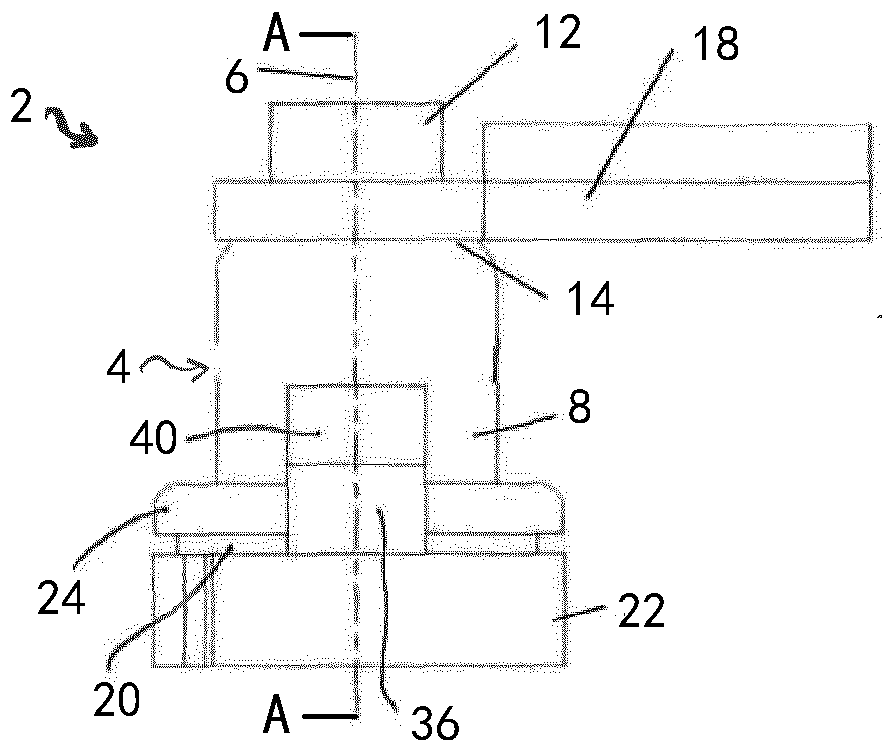
[0030] now refer to figure 1 , shows the injector cup assembly 2 having the fuel injector cup 4 formed from sheet material as a single piece. The fuel injector cup 4 is substantially cylindrically formed about an axis 6 . The fuel injector cup 4 has a main body portion 8 containing a fuel injector 5 ( figure 1 Not shown in ) the volume 10 of the fuel inlet port. As shown, at the outer upstream end of the injector cup, the injector cup 4 has a coaxial tubular stub 12 having a reduced outer diameter relative to the diameter of the main body portion 8 to form an annular shoulder 14 . The stub contains a fuel inlet port 16 to which a fluid tube (not shown) is connected to provide a hydraulic connection between the volume 20 and a fuel source, typically in the form of a common rail (not shown) .

[0031] At the end of the volume in the injector cup 10 opposite the stub 12 , the volume in the injector cup 10 opens to receive the inlet end of the fuel injector 5 .

[0032] now a...


PUM


Abstract

Various embodiments include a fuel injector assembly for an internal combustion engine comprising: an injector cup; a securing device to fasten the injector cup to the engine; wherein a first end of the injector cup remote from the fuel inlet port comprises an outwardly extending flange; a connector abutting the flange, wherein the injector cup and the fuel injector are secured together through the connector; and a fastening bracket supported on the flange, wherein the injector cup and the connector are secured through the fastening bracket by a fastening device. The fastening device comprises a U-shaped clip with a first arm disposed between a clamping face of the fastening device and the fastening bracket and a second arm generally parallel to the first arm disposed on the opposite side of the fastening bracket.

Description

technical field [0001] The present disclosure relates to an assembly for mechanically and hydraulically coupling a fuel injector cup to a fuel injector, and a fuel injector cup assembly for an internal combustion engine. Background technique [0002] Fuel injectors are widely used in internal combustion engines, where they are arranged to inject fuel into the intake manifold of the internal combustion engine or directly into the combustion chambers of cylinders of the internal combustion engine. [0003] The fuel injectors of a multi-cylinder internal combustion engine are connected to a fuel source called a common rail, each of the fuel injectors being hydraulically and mechanically connected to the common rail through a fuel injector cup. The injector cups themselves are connected to the common rail by supply pipes through which high pressure fuel is supplied via the cups to the fuel injectors. [0004] Such cup assemblies are known from the prior art, see for example US ...

Claims


Application Information

Patent Timeline
Patent Type & Authority Patents(China)
IPC IPC(8): F02M55/02F02M61/14F02M61/18
CPCF02M55/025F02M61/14F02M2200/803F02M2200/85F02M2200/855F02M2200/8023F02M2200/9038F02M2200/9053
Inventor G.塞拉D.马泰尼
Owner VTESCO TECH GMBH
Why Eureka
Try Eureka