Magnetic head assembly and magnetic disc driver

A magnetic head assembly and magnetic head technology, which is applied in the field of disk drives, can solve the problems of easy damage of the magnetic head and inconvenient installation of the magnetic head assembly, and achieve the effect of convenient assembly and avoiding damage

Inactive Publication Date: 2007-11-07
YITUO SCI & TECH CO LTD SHENZHEN
View PDF0 Cites 0 Cited by
  • Summary
  • Abstract
  • Description
  • Claims
  • Application Information

AI Technical Summary

Problems solved by technology

[0004] The technical problem to be solved by the present invention is: in the traditional disk drive assembly, the prob

Method used


Image

  • Magnetic head assembly and magnetic disc driver
  • Magnetic head assembly and magnetic disc driver
  • Magnetic head assembly and magnetic disc driver

Examples


Embodiment Construction

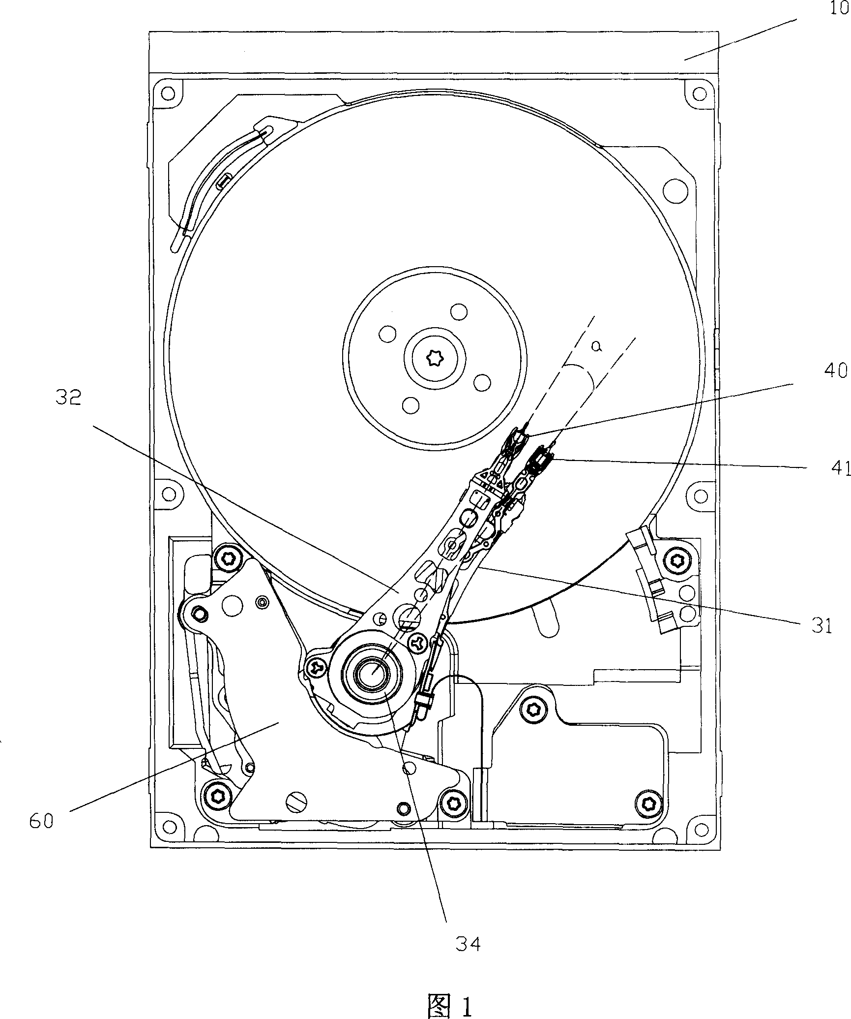
[0015] Please refer to FIG. 1 to FIG. 3 , a novel disc drive of the present invention includes a disc base 10 , a magnetic head assembly and a voice coil motor 60 for driving the magnetic head assembly to rotate.

[0016] A disk installation area is formed in a recess on the disk base 10, and at least one disk (not shown) is installed in the disk installation area. The magnetic head assembly is installed on one side of the disk.

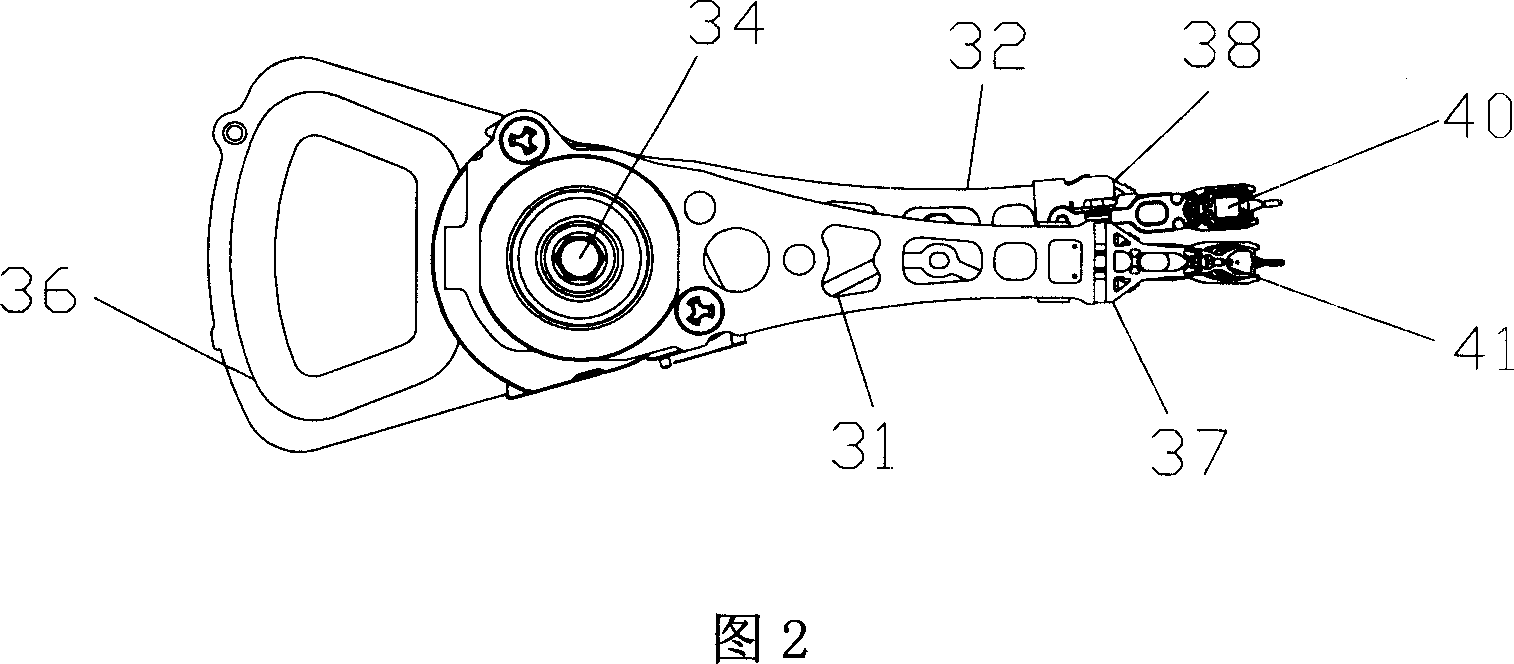
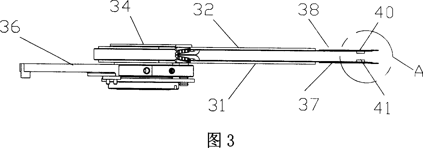
[0017] The magnetic head assembly includes several suspension arms. In this embodiment, two suspension arms 31 and 32 are used. Ends of the cantilever 31 and the cantilever 32 are respectively connected to elastic carrying arms 37 and 38 . Magnetic heads 41 and 40 are suspended from the ends of the carrying arms 37 and 38 respectively. The cantilevers 31 , 32 are fixed on a bearing 34 , and the bearing 34 is supported on a rotating shaft (not shown) on the base 10 .

[0018] Please also refer to FIG. 4 , the magnetic heads 41 and 40 at the ends of...


PUM


Abstract

This invention relates to a new type of head component including a pair of cantilevers, the end of each of which is connected with an elastic loading arm and a head is hung on the end of the arm and heads at the ends of the two loading arms are used in reading data on up and down two sides of a disc and set staggeredly. This invention also discloses a disc drive using said head component.

Description

【Technical field】 [0001] The invention relates to a disk drive, in particular to a disk drive which can facilitate the installation of a magnetic head assembly while ensuring that the magnetic head is not damaged. 【Background technique】 [0002] Existing disk drives generally include a base and a disk installed in the base. The disk surface is covered with magnetic media and is mounted on a spindle motor shaft that rotates at a constant high speed. The reading and writing of data on the magnetic disk is accomplished by the magnetic head on the magnetic head assembly driven by the voice coil motor. The magnetic head is installed at the ends of the two carrying arms of the magnetic head assembly face to face. Because the carrying arm has elasticity, when it is in a free state, two magnetic heads facing each other will stick together to cause damage to the magnetic head. [0003] In the assembly of the traditional magnetic head assembly, tools such as comb teeth are needed t...

Claims


Application Information

Patent Timeline
IPC IPC(8): G11B5/48G11B21/16
Inventor 许铭癸
Owner YITUO SCI & TECH CO LTD SHENZHEN
Why Eureka
Try Eureka