Tail yarn holding device of spinning machine

A technology of holding device and spinning machine, applied in textile and paper making, etc., can solve the problem of not being able to shorten the length of tail yarn

Inactive Publication Date: 2007-11-14
TOYOTA IND CORP
View PDF1 Cites 3 Cited by
  • Summary
  • Abstract
  • Description
  • Claims
  • Application Information

AI Technical Summary

Problems solved by technology

In this way, in order to prevent the failure of holding the yarn, the length of the tail yarn cannot be shortened

Method used


Image

  • Tail yarn holding device of spinning machine
  • Tail yarn holding device of spinning machine
  • Tail yarn holding device of spinning machine

Examples


Embodiment Construction

[0017] A ring spinning frame according to an embodiment of the present invention will now be described with reference to FIGS. 1A-4B.

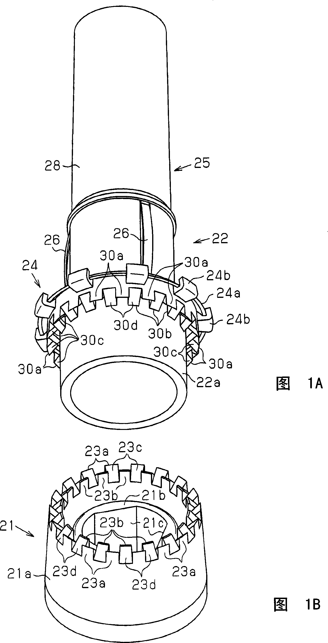
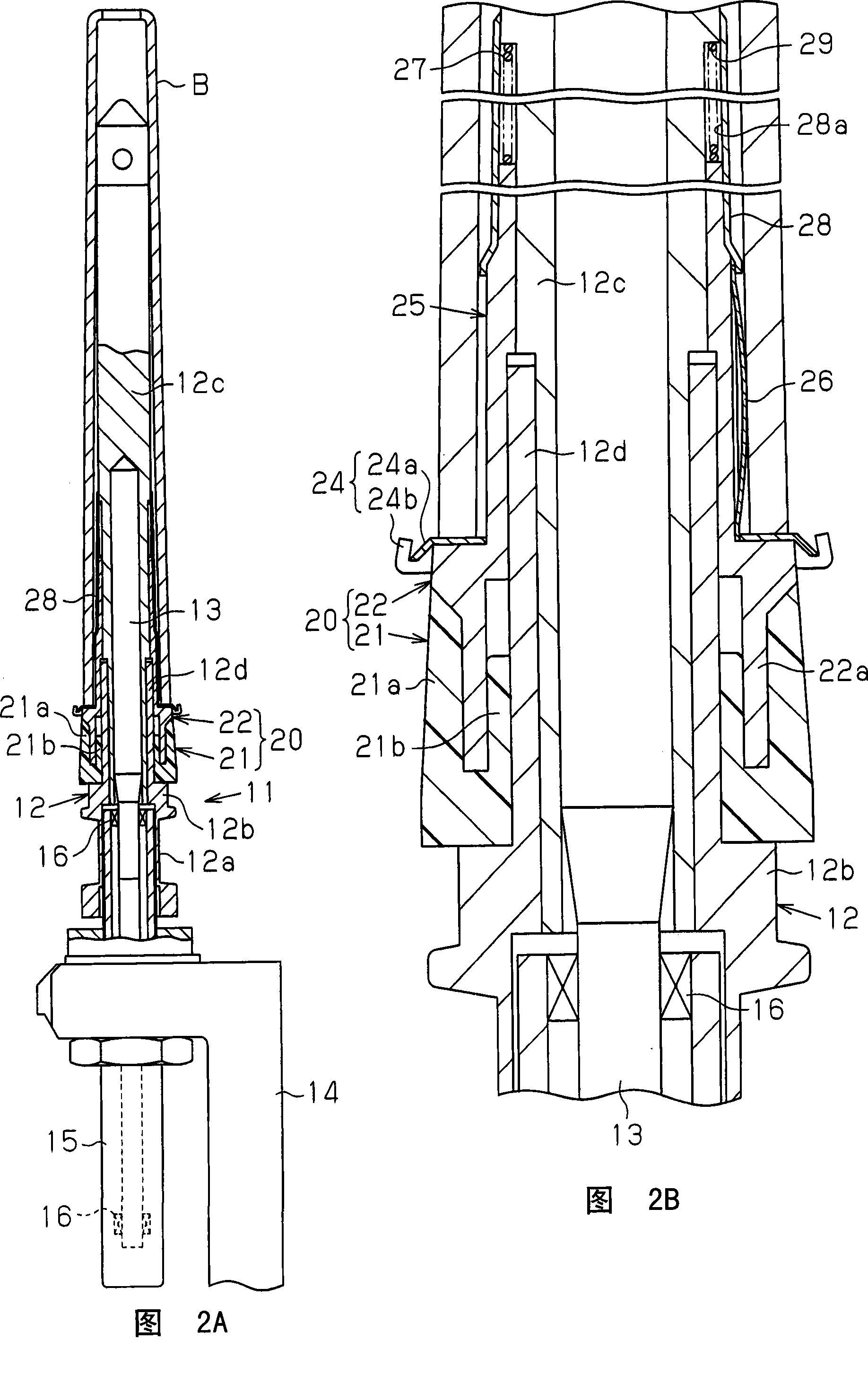
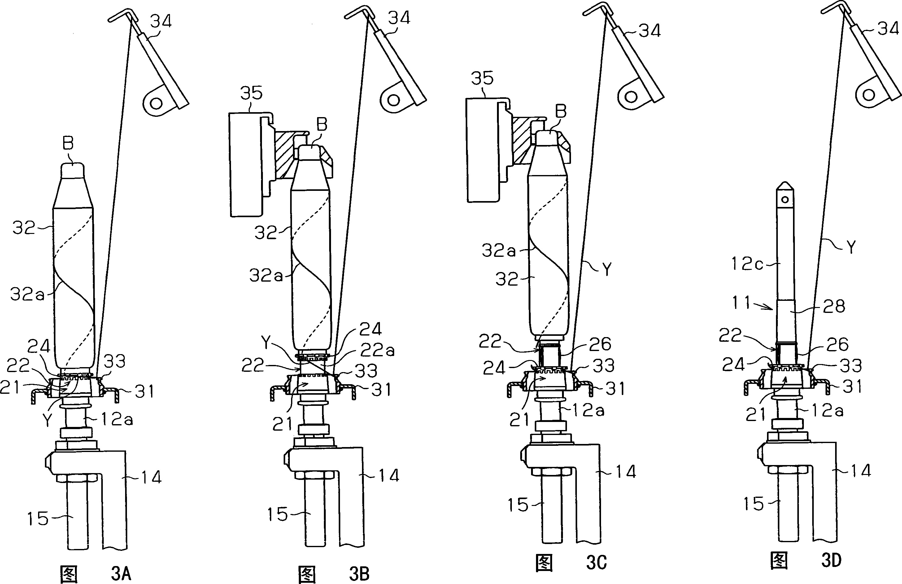
[0018] As shown in FIG. 2A, the spindle 11 has a blade portion 12 and a spindle shaft 13. As shown in FIG. The spindle shaft 13 is rotatably supported by a spindle foot 15 fixed to a lower dragon bar 14 with a bearing 16 . The blade portion 12 has a foot 12b and blades 12c. The foot 12b has a belt engaging the portion 12a, and the blade 12c is fitted to the upper portion of the foot 12b. The bobbin B is connected to the blade 12c. Spindle 13 is a molded insert with blade 12C.

[0019] The foot 12b has a mounting member 12d on the upper portion. A tail yarn holding part 20, which functions as a tail yarn holding device, is installed on the mounting part 12d. The tail yarn holding part 20 includes an annular lower holding part 21 and an annular upper holding part 22 . In this embodiment, the lower grip member 21 is formed of an elastic bod...


PUM


Abstract

This invention relates to a tail thread gripping device comprising an annular bottom gripping member and an annular upper part gripping member. The bottom gripping member can reciprocate relative to spindle. The bottom gripping member comprises first tooth, which are composed of tooth with inward tooth flank facing to the inside of the said bottom gripping member and tooth with outward tooth flank facing to the outside of the said bottom gripping member, and the first tooth with inward tooth flank and the first tooth with outward tooth flank are alternately installed at the circumferencial direction of the upper part gripping member. The annular upper part gripping member comprises a number of second tooth, which are composed of tooth with inward tooth flank facing to the inside of the said bottom gripping member and tooth with outward tooth flank facing to the outside of the said bottom gripping member, and the second tooth with inward tooth flank and the second tooth with outward tooth flank are alternately installed at the circumferencial direction of the upper part gripping member. The inward tooth flank of the first tooth faces to the outward tooth flank of the second tooth, at the same time the outward tooth flank of the first tooth faces to the inward tooth flank of the second tooth.

Description

technical field [0001] The present invention relates to a tail yarn holding device in a spinning machine, in particular to a tail yarn holding device used in a spinning machine. Winding of the thread, the bobbin is lifted from the spindle and removed by the doffing device. Background technique [0002] In ring spinning machines, the yarn is wound by a traveler, or in ring twisting machines, the exchange of bobbins is carried out automatically in order to replace full bobbins with empty bobbins. When restarting the spinning machine after bobbin replacement, the yarn connected to the roller unit needs to reach the spindle as it passes through the traveler so that the yarn can be automatically wound around the new empty bobbin. Japanese Laid-Open Patent No. 2004-339620 discloses a tail yarn cutting device which satisfies the above-mentioned needs and is capable of satisfying the remaining yarn length or tail yarn length on the spindle foot. [0003] The tail yarn cutting devi...

Claims


Application Information

Patent Timeline
Patent Type & Authority Applications(China)
IPC IPC(8): D01H9/00D01H9/16
Inventor 药司诚
Owner TOYOTA IND CORP
Why Eureka
Try Eureka