
Density-dependent sharpening

A density and sharpening technology, applied in image enhancement, instrumentation, computing, etc.

Inactive Publication Date: 2007-11-14
MITCHAM GLOBAL INVESTMENTS
View PDF1 Cites 2 Cited by
  • Summary
  • Abstract
  • Description
  • Claims
  • Application Information

AI Technical Summary

Problems solved by technology

As a result, edges printed at low density are not as sharp as equivalent edges printed at high density

Method used


Image

  • Density-dependent sharpening
  • Density-dependent sharpening
  • Density-dependent sharpening

Examples


Embodiment Construction

[0033] Referring to FIG. 6A , a block diagram of a sharpening system 600 according to one embodiment of the present invention is shown. System 600 includes an original image 602 that has been sharpened by a density-dependent sharpening filter 604 to produce a sharpened image 606 . Referring to FIG. 7A , there is shown a flowchart of a method 700 that represents a straightforward way for the system 600 to perform density-dependent or gray-level-dependent sharpening. In general, method 700 performs filtering in the spatial domain and varies filter support and shape from one region (eg, pixel) to another.

[0034] More specifically, the method 700 unrolls a loop for each region R (eg, each pixel) in the original image 602 (step 702 ). Method 700 uses larger region S 0 The local density d of the identified region R, the larger region S 0 is a superset of R (step 704), and sharpening filter 604 parameters are selected according to the density d (step 706). Examples of these par...


PUM


Abstract

A sharpening filter is disclosed for performing density-dependent sharpening on digital images. In one embodiment, a digital image to be sharpened is decomposed into a plurality of high-pass versions of the image at different resolutions. These high-pass images are gained at each resolution and recombined with the original image to produce a sharpened version of the image. The gains that are applied at each resolution are density-dependent. As a result, the effects of density-dependent blurring are counteracted, such that the sharpness of the final printed image is independent of the print density. Techniques are disclosed for performing such density-dependent sharpening with a high degree of computational efficiency.

Description

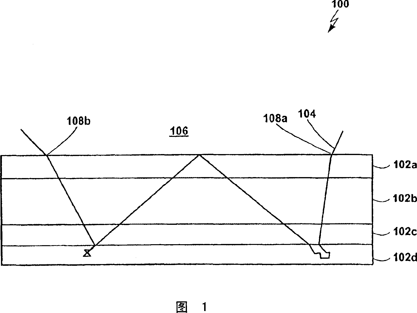
[0001] Cross References to Related Applications [0002] This application is related to US Patent No. 6801233B2, commonly entitled "Thermal Imaging System," which is incorporated herein by reference. technical field [0003] The present invention relates to digital image processing, and more particularly, to techniques for sharpening digital images. Background technique [0004] The above-cited patent entitled "Thermal Imaging System" discloses a print medium having multiple color-forming layers. Referring to FIG. 1 , there is shown a schematic diagram of the structure of one embodiment of a medium 100 disclosed in the above-referenced patent application. Two of the colorants, yellow and magenta (the two colorants are shown as one layer for purposes of illustration, but they generally exist in separate layers) 102a, are near the top of the media 100, while the third The first colorant, cyan 102c, is separated from the first two colorants by a relatively thick matrix 102b w...

Claims


Application Information

Patent Timeline
Patent Type & Authority Applications(China)
IPC IPC(8): H04N1/409
CPCH04N1/4092G06T5/004G06T5/75
Inventor S·S·萨奎布
Owner MITCHAM GLOBAL INVESTMENTS
Learn More