
Upstream channel bonding in a cable communications system

A technology of cable TV and channel binding, applied in the field of data transmission, which can solve problems such as unrealistic

Active Publication Date: 2007-11-14
AVAGO TECH INT SALES PTE LTD
View PDF0 Cites 24 Cited by
  • Summary
  • Abstract
  • Description
  • Claims
  • Application Information

AI Technical Summary

Problems solved by technology

However, using very high-order modulations (e.g., 1024QAM) and wider channels upstream is currently impractical

Method used


Image

  • Upstream channel bonding in a cable communications system
  • Upstream channel bonding in a cable communications system
  • Upstream channel bonding in a cable communications system

Examples


Embodiment Construction

[0046] 1 Overview

[0047] 1.1 System overview

[0048] 1.2 Introduction to Channel Bonding

[0049] 1.3 Terminology

[0050] 2. Traffic segmentation

[0051] 2.1 Segment overview

[0052] 2.2 Continuous cascading and fragmentation

[0053] 2.2.1 Traditional DOCSIS Concatenation and Fragmentation

[0054] 2.2.2 Continuous concatenation and fragmentation according to an embodiment of the present invention

[0055] 2.2.3 Segments without a segment header

[0056] 3. Request bandwidth

[0057] 3.1 Request Mechanism

[0058] 3.2 Piggybacking requests

[0059] 3.2.1 Exemplary Rules for Piggybacking Requests Using Section Headers

[0060] 3.2.2 Exemplary Rules for Disabling Piggybacking Requests Under Segment Headers

[0061] 3.3 Contention requesting

[0062] 4. Allowed bandwidth

[0063] 5. Baseline Privacy Impact

[0064] 5.1 Conventional DOCSIS communication decryption

[0065] 5.2 Communication decryption of bound uplink channel

[0066] 5.2.1 CM forces a single...


PUM


Abstract

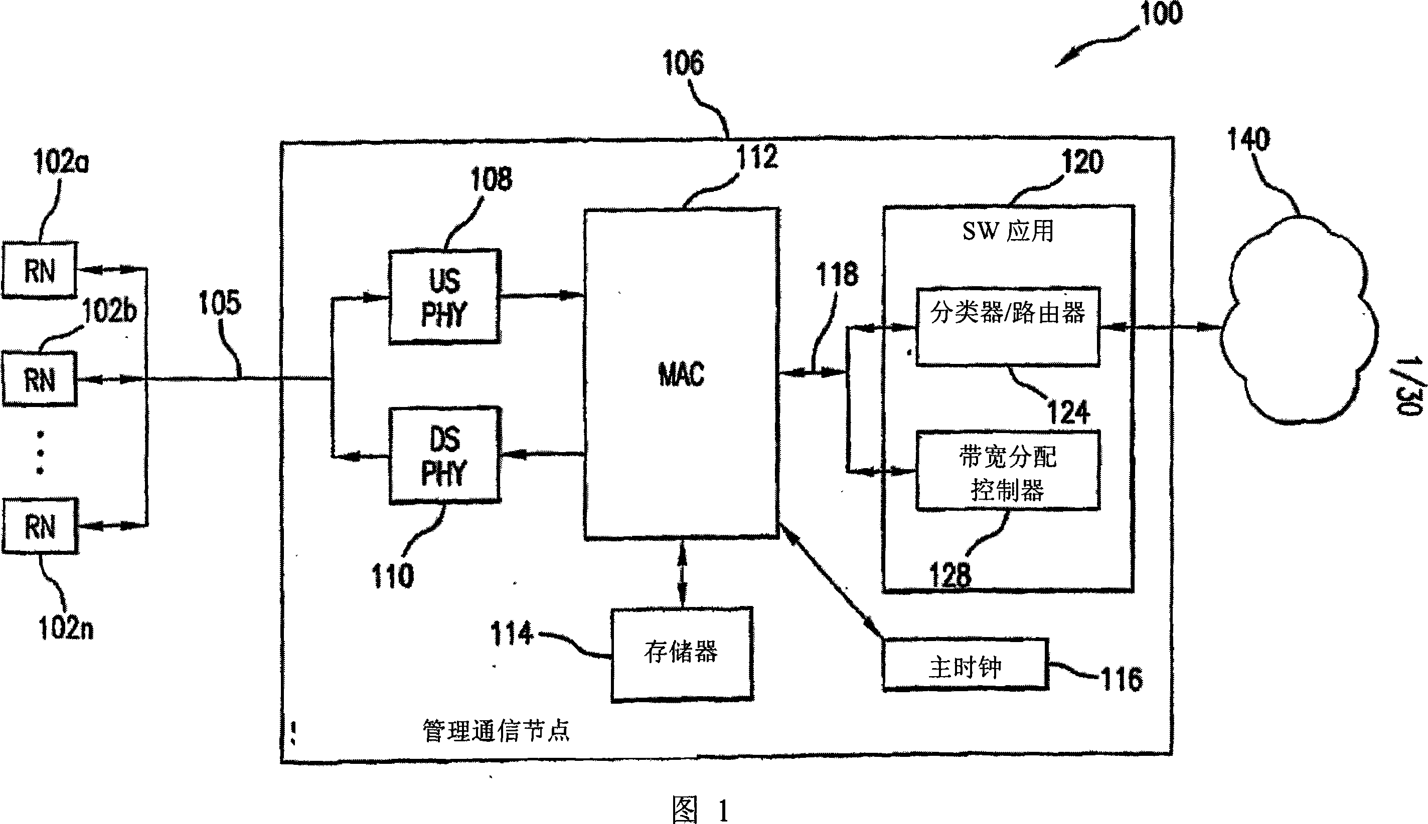
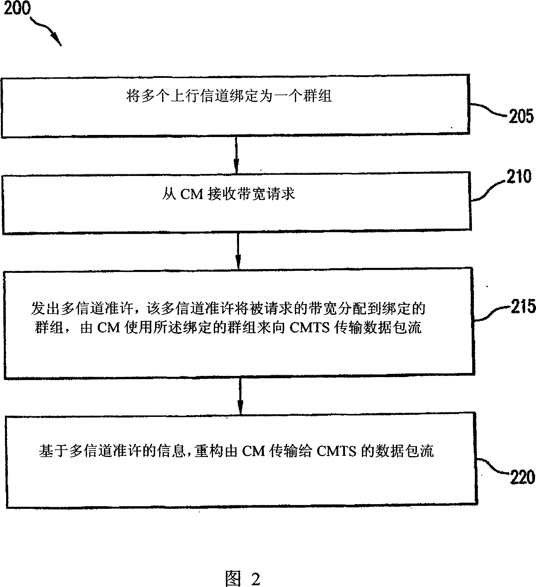
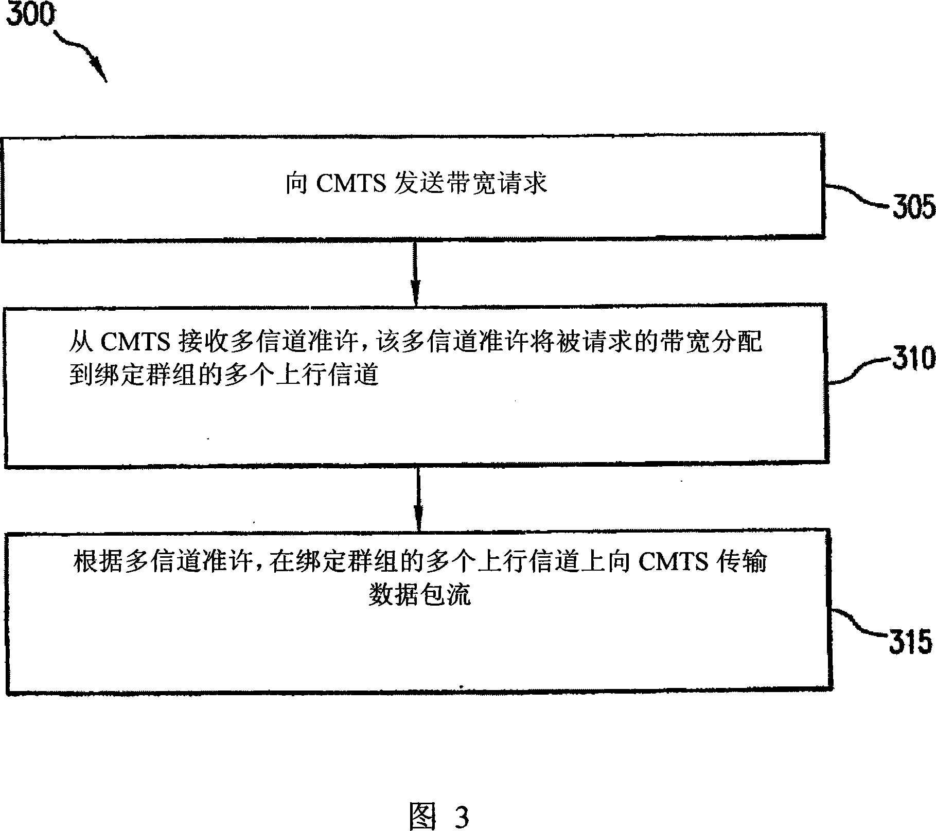
A method for increasing upstream bandwidth per cable modem user in a cable communications system that includes a cable modem termination system (CMTS) and a plurality of cable modems is provided. The method permits a cable modem to transmit data to the CMTS on multiple upstream channels simultaneously using a technique called 'channel bonding'. 'Channel bonding' allows smaller bandwidth upstream channels to be bonded together to create a larger bandwidth pipe.

Description

technical field [0001] The present invention relates to a method of transmitting data in a data communication system, such as but not limited to a cable television communication system. Background technique [0002] Conventional cable television communication systems typically use a cable modem headend that manages communications with multiple cable modems. The headend defines the upstream operating characteristics that enable the cable modem to send the carrier signal upstream to the headend. This upstream can include multiple channels that can be assigned to cable modems. These channels are independent of each other by operating at different frequencies. [0003] One or more cable modems transmit carrier signals carrying requests and / or data to the headend using designated frequency channels. The demodulator at the headend receives these uplink signals, and the modulator is connected to the physical spectrum, and the physical spectrum is connected to the cable TV modem ...

Claims


Application Information

Patent Timeline
Patent Type & Authority Applications(China)
IPC IPC(8): H04N7/173H04J3/16H04L45/243
CPCH04L43/00H04L12/26H04L49/90H04L45/245H04L12/2801H04N7/17309H04L49/9094H04L47/125Y02B60/33H04L47/35H04L47/10H04J3/1694H04N21/6168Y02D30/50H04L47/43H04L47/431
Inventor 莉萨·沃伊特·丹尼奈基·罗伯塔·潘特利斯斯科特·A·霍洛姆斯维克托·T·霍约翰·丹勒特·霍顿大卫·迈克尔·普伦
Owner AVAGO TECH INT SALES PTE LTD
Learn More