
Portable electronic terminal and data processing system

a technology of electronic terminals and data processing systems, applied in data processing applications, instruments, commerce, etc., can solve problems such as inability to meet the needs of multiple shopping establishments or varying user needs, cumbersome separate cards, and insufficient security of prior art systems, so as to achieve the effect of improving economics and programmability

Inactive Publication Date: 2007-01-30
SYMBOL TECH INC
View PDF24 Cites 291 Cited by
  • Summary
  • Abstract
  • Description
  • Claims
  • Application Information

AI Technical Summary

Benefits of technology

[0012]It is yet a further object of the present invention to provide an improved portable terminal which can be used by a given consumer in both a home and store location, and can perform enhanced shopping database management.
[0013]It is a further object of the present invention to provide an improved cradle system which provides modular scalability and multiple communication alternatives.
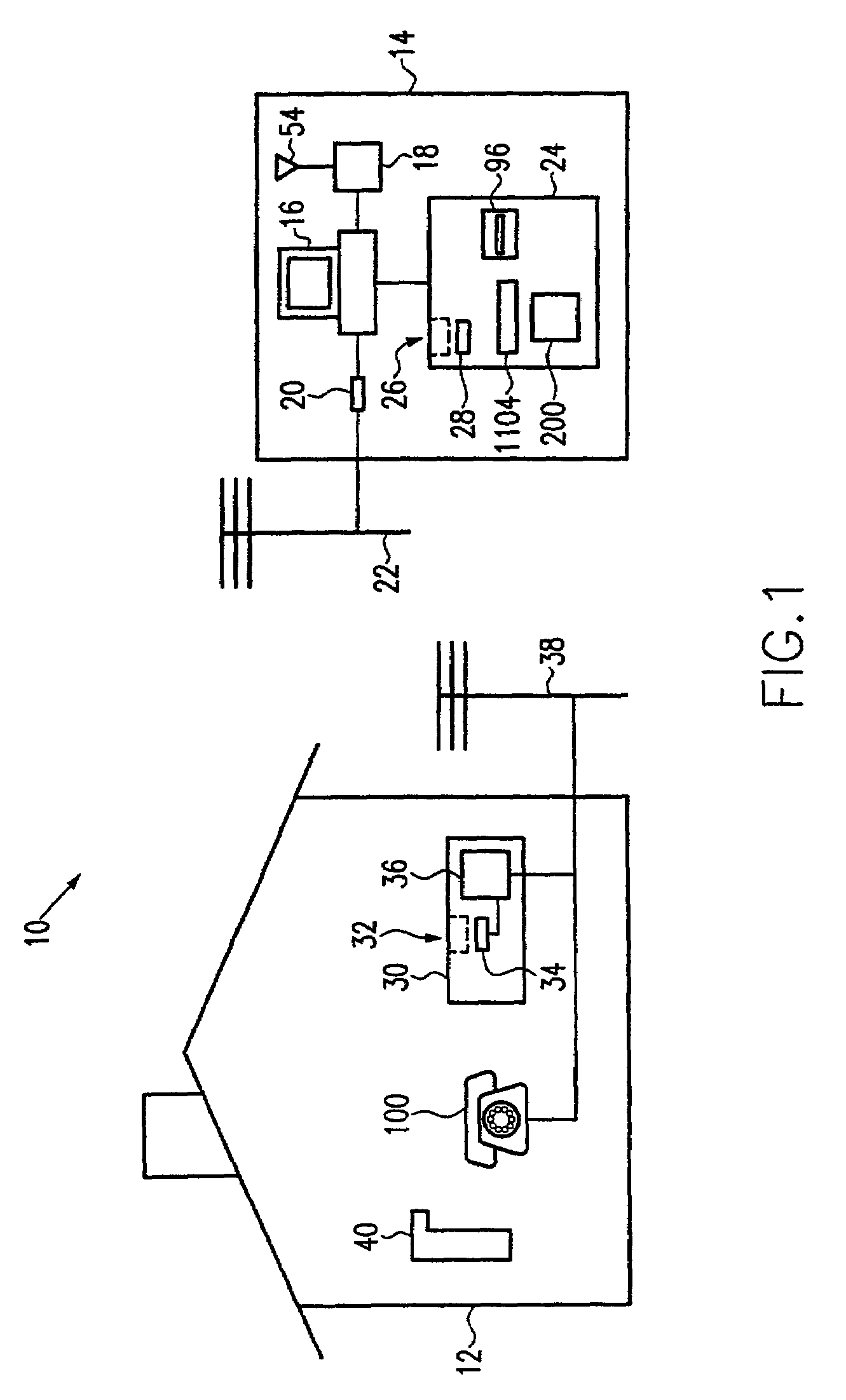
[0020]The present invention also provides a method of placing an order for items including at least one of goods and services. The method includes the steps of reading bar codes associated with the items via a two-way terminal data interface of a portable terminal; storing data associated with the bar codes in a memory of the portable terminal; and then transferring the data associated with the bar codes to a host computer for storage in a shopping list database. The transferring step includes the sub-steps of transferring the data associated with the bar codes from the memory of the portable terminal to the two-way terminal data interface of the portable terminal; transferring the data associated with the bar codes from the two-way terminal data interface to a data interface of either a kiosk portable terminal-receiving station of a shopping establishment kiosk cradle or a home portable terminal-receiving station of a home cradle; and then transferring the data to the host computer. The method further includes transmitting identifying indicia to the host computer to identify the user to the host computer; the indicia can be the aforementioned intrinsic identifying indicia contained in the portable terminal. A telephone “caller ID” function can be employed for additional security.
[0021]The present invention also provides for an improved terminal design and cradle assembly which may be utilized in numerous applications such as, for example, inventory control, package tracking and health maintenance tracking. The improved terminal provides for improved power management, self-diagnosis, cradle communications and system architecture as well as improved economics and programmability. In combination, the present invention also provides for an improved field configurable cradle assembly which permits the use of multiple terminals at a location and simultaneous data transfers over an industry standard network architecture such as “Ethernets” and RS232 serial communication channels. The cradles are programmable to control multiple terminal data communications and may be attached and / or stacked to each other to provide multiple physical layouts at a user receiving area. The cradles may then be used to “synch” data through a central station and to transfer data to various destinations.

Problems solved by technology

However, they exhibit certain deficiencies.
For example, they may not provide adequate security, or may require cumbersome separate cards for security purposes.
Further, prior art systems may not be able to deal effectively with multiple shopping establishments or varying user needs.

Method used


Image

  • Portable electronic terminal and data processing system
  • Portable electronic terminal and data processing system
  • Portable electronic terminal and data processing system

Examples


first embodiment

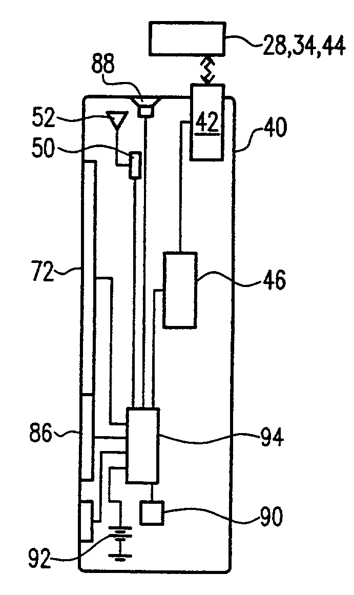
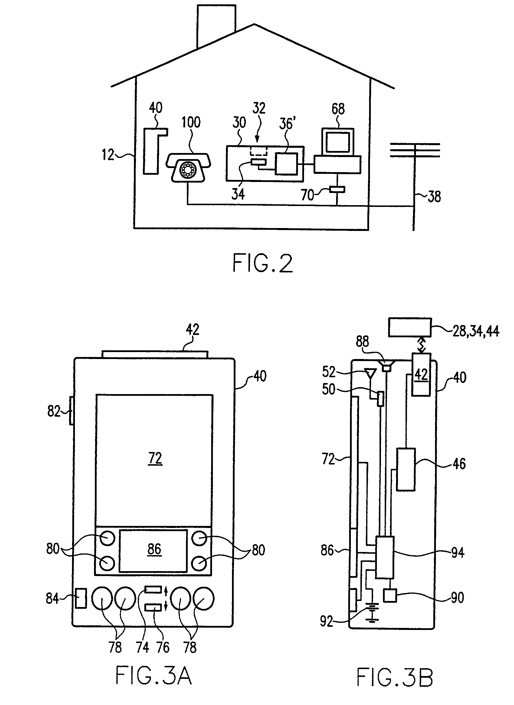
[0066]The system also includes a portable terminal 40. It will, of course, be appreciated that normally there will be many such terminals for the different users of the system. However, only a single terminal 40 is shown in the drawings in order to clearly illustrate the principles of the present invention. Referring now to FIGS. 3A and 3B, portable terminal 40 includes a two-way data interface 42, such as a laser or CCD bar code reader, which is configured to read bar codes associated with items 44 related to shopping. The items 44 can be, for example, empty packages of items which it is desired to re-stock; items from a catalog representing goods or services; and the like. Portable terminal 40 also includes a memory 46 coupled to the two-way data interface 42 for storing data associated with the bar codes from the items 44. Memory 46 could include RAM and also identification ROM circuitry discussed below. Thus, the memory would be used to store lists of products desired for purcha...

fourth embodiment

[0109]FIG. 10 shows the portable terminal of the present invention. This embodiment is similar to the embodiment of FIG. 9A, but in addition includes two bar code activation buttons 82 disposed on the left and rights of the terminal each for triggering bar code reading by the user. As shown, two bar code activation buttons 82 disposed on the two sides the terminal housing allow the user to simultaneously view the terminal display while viewing the visible light source upon activation of the bar code scanner.

[0110]FIG. 11 shows a high-level block diagram of the hardware architecture for the portable terminal of the present invention. The portable terminal includes a scanning device 910 for reading bar code, a scanner decoder 920 coupled to the scanning device 910, a communications interface / memory board 930 coupled to the scanner decoder 920, and a main processing board 940 coupled to the board 930. Further details of the hardware architecture are described with reference to the deta...

second embodiment

[0115]FIG. 13 is a block diagram showing a portable terminal hardware architecture in accordance with the present invention. The embodiment of FIG. 13 is a modified version of the embodiment of FIG. 12 wherein a wireless communications device 970 is coupled to the communications interface 930 and a corresponding antenna. As further shown in FIG. 14, the communications device 970 is the Spectrum 24™ radio, available from Symbol Technologies, Inc., which is coupled via a PCMCIA or equivalent interface 953 included in the ASIC 933. In an alternative embodiment, the portable device is inserted into a sled (not shown) that mates to the synchronization port 943.

[0116]In the event multiple users of terminals exist, it may be preferable to provide multiple cradles which are networked together or otherwise connected to a destination host.

[0117]FIG. 15 shows a perspective view of a stackable cradle assembly 1000 according to a preferred embodiment of the present invention. As shown in FIG. 15...


PUM


Abstract

The present invention relates to a personal shopping system for combined use in both the home of a user and a shopping establishment. The system includes a host computer which is coupled to a host modem and, optionally, to at least one wireless multi-access point. At least one shopping establishment kiosk cradle is employed to interface with a portable terminal which is also part of the system. The portable terminal can be used in both the shopping establishment and the home of the user. It is configured to read bar codes associated with items related to shopping, and includes a memory, a bar code reader, a wireless transceiver, and a data interface. The data interface of the terminal communicates with a data interface of the shopping establishment kiosk cradle. A home cradle for the portable terminal is also provided and is adapted to remain in the home of the user. It includes a home portable terminal-receiving station and a home data interface to communicate with the data interface of the portable terminal. A home data transfer circuit is also included to permit data exchange between the home data interface and the modem coupled to the host computer.

Description

RELATED APPLICATIONS[0001]This application is a continuation of application Ser. No. 09 / 232,142 filed on Jan. 16, 1999 now U.S. Pat. No. 6,640,214, which is a continuation-in-part of application Ser. No. 09 / 087,086 filed on May 29, 1998 now U.S. Pat. No. 6,101,483.FIELD OF USE[0002]This invention relates generally to an improved data processing system which may be used inter alia with a system for ordering and supplying selected goods and services. More specifically, this invention relates to a portable terminal which may be used in conjunction with a personal shopping system which can be used in both a home of a user and a shopping establishment. The portable terminal can be further used, for example, by health care professionals to track medications and patient status, and by postal carriers to track mail deliveries.BACKGROUND OF THE INVENTION[0003]Hand-held computer terminals are well known in the prior art for many different applications, including their use in consumer portable...

Claims


Application Information

Patent Timeline
IPC IPC(8): G06Q30/00G06Q10/08G06Q20/20G06Q20/34G06Q30/06G07F7/02
CPCG06Q10/087G06Q10/0875G06Q20/202G06Q20/343G07F7/02G06Q30/0617G06Q30/0633G06Q30/0641G06Q30/06
Inventor PETROVICH, ADAMROSLAK, THOMAS K.SWARTZ, JEROMEBRIDGELALL, RAJ
Owner SYMBOL TECH INC
Learn More