Method for reinforcing measurement precision of substrate structure coordinate

A high-precision, coordinate technology, used in measuring devices, optical devices, instruments, etc., can solve problems such as the influence of measurement time

Inactive Publication Date: 2007-11-21
VISTEC SEMICON SYST
View PDF2 Cites 2 Cited by
  • Summary
  • Abstract
  • Description
  • Claims
  • Application Information

AI Technical Summary

Problems solved by technology

Incorporating it in existing methods such that m

Method used


Image

  • Method for reinforcing measurement precision of substrate structure coordinate
  • Method for reinforcing measurement precision of substrate structure coordinate
  • Method for reinforcing measurement precision of substrate structure coordinate

Examples


Embodiment Construction

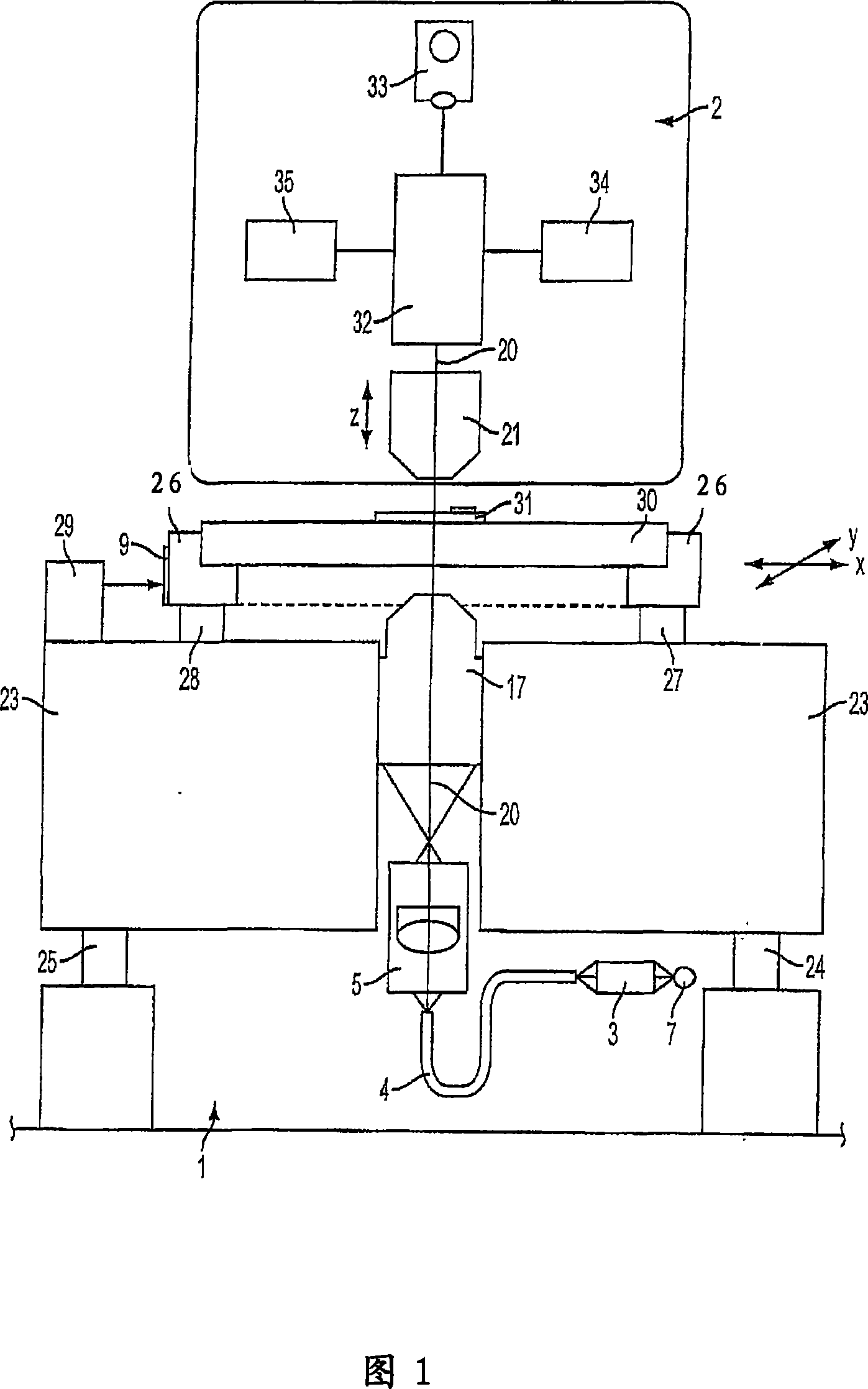
[0050] A coordinate measuring device of the type shown in FIG. 1 has been explained in detail in the introductory part of the description.

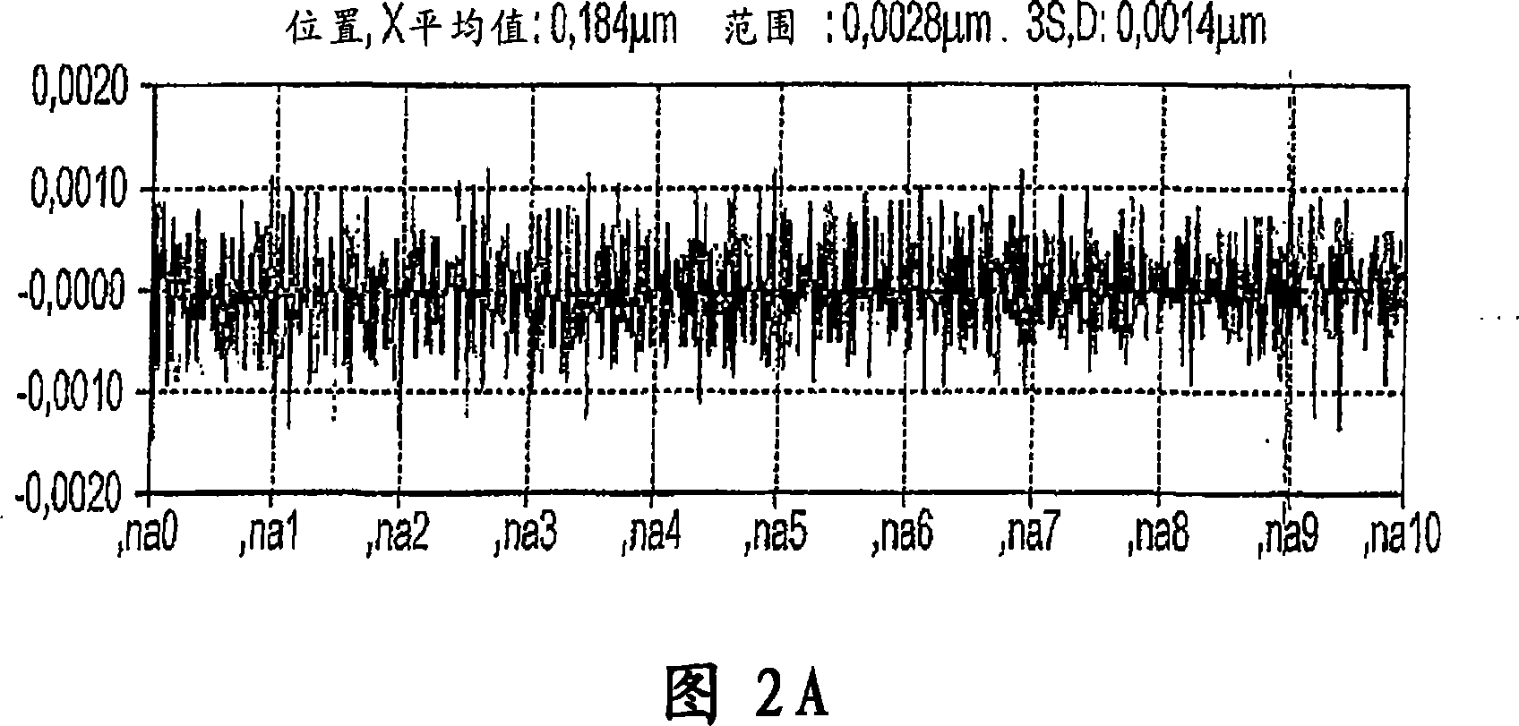
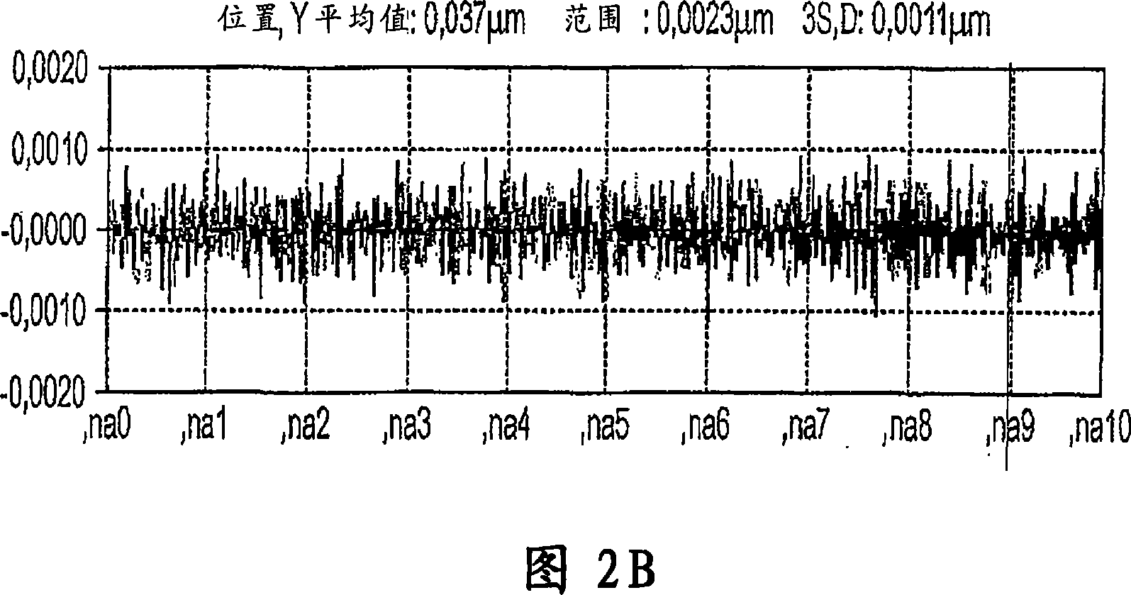
[0051] The repeatability or reproducibility of this coordinate measuring device is usually determined in the factory by measuring a 15x15 point measurement grid (measurement area 6 inches, 152x152 mm). The value of three times the standard deviation (3σ) is usually determined after 20 measurements of the coordinates obtained in the X and Y coordinate directions. This maximum value of three times the standard deviation is indicative of repeatability and thus machine performance.

[0052] If measurements are made locally on defined mask positions (i.e. without traversing the X / Y measurement stage in this case), then this is an indication of short-term reproducibility (here, 20*100 measurements*4 seconds = 2.2 hours). This measurement gives an indication of the repeatability over a short period of time (so-called needle test).

[0053] Th...


PUM


Abstract

The invention provides a method for the high-precision measurement of coordinates of at least one structure on a substrate. A stage traversable in X/Y coordinate directions is provided, which is placed in an interferometric-optical measuring system. The structure on the substrate is imaged on at least one detector (34) via a measuring objective (21) having its optical axis (20) aligned in the Z coordinate direction. The structure is imaged with the so-called Dual Scan. Systematic errors can thereby be eliminated.

Description

technical field [0001] The invention relates to a method for high-precision measurement of the coordinates of at least one structure on a substrate placed on a platform movable in the X / Y coordinate direction in an interferometric optical measurement system. The structures on the substrate are imaged onto the detector via a measurement objective whose optical axis is aligned in the Z coordinate direction. Background technique [0002] The method for mapping substrates ( A measuring device for measuring structures on a wafer or mask). The description given here is the basis for a coordinate measuring device. Since the invention can be advantageously used with said measuring device and will be mainly described with reference to said measuring device without prejudice to its general applicability, reference will be made hereinafter to the accompanying drawings 1 to describe this measuring device. A well-known measuring device 1 is used for measuring structures 31 on samples...

Claims


Application Information

Patent Timeline
IPC IPC(8): G01B9/02G01B11/30
Inventor 伯塞尔・汉斯・阿图尔沙夫・安地列斯
Owner VISTEC SEMICON SYST
Why Eureka
Try Eureka