Method and device for controlling video record and synchronized-controlling unit

A video recording and control method technology, applied in the multimedia field, can solve the problems of audio and video out of sync, low frame rate of actual video recording, etc., and achieve the effect of reducing out of sync

Inactive Publication Date: 2010-06-09
VIMICRO CORP
View PDF4 Cites 0 Cited by
  • Summary
  • Abstract
  • Description
  • Claims
  • Application Information

AI Technical Summary

Problems solved by technology

[0014] Embodiments of the present invention provide a video recording control method, device, and synchronous control unit, which are used to solve the problem that the actual video frame rate of the video file is lower than the set value due to the decrease of the frame rate of the image sensor or the delay of the timer interrupt processing during the audio recording process. Fix the video frame rate, resulting in the problem of audio and video out of sync

Method used


Image

  • Method and device for controlling video record and synchronized-controlling unit
  • Method and device for controlling video record and synchronized-controlling unit
  • Method and device for controlling video record and synchronized-controlling unit

Examples


Embodiment 1

[0108] combine Figure 7 , Figure 8 The schematic structural diagram of the video recording control device provided by the embodiment of the present invention is shown, and the specific flow of the video recording control method in this embodiment is as follows:

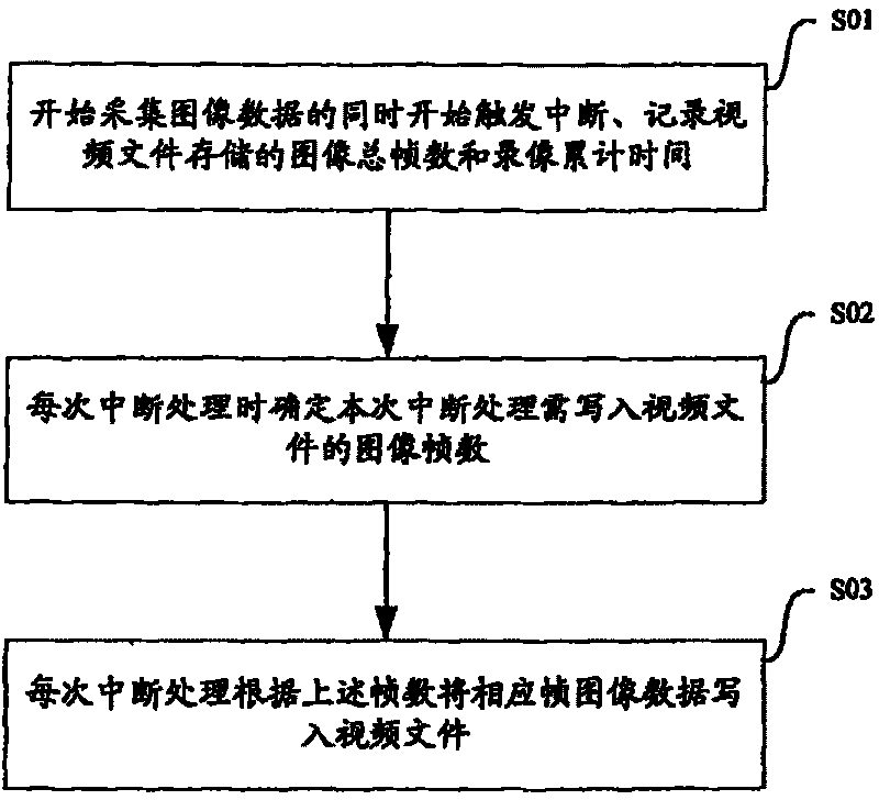
[0109] Step S101, when the image sensor 11 starts to collect image data, the control subunit 121 in the synchronous control unit 12 sets the interrupt frequency of the interrupt trigger subunit 122 to be the same as the set video frame rate, and controls the interrupt trigger subunit 122, frame number The recording subunit 123 and the time recording subunit 124 start working;

[0110] Step S102, the interrupt triggering subunit 122 triggers the interrupt processing subunit 125 to perform interrupt processing according to the set interrupt frequency;

[0111] Step S103, the interrupt processing subunit 125 acquires the cumulative video recording time when the interrupt is triggered from the time recording subunit 1...

Embodiment 2

[0120] The Timer control is also called a timer, which can trigger events at a certain time interval. The most important property of the timer is the Interval property, which is used to set the time interval between timer events in milliseconds. In Embodiment 1, a timer is used as an interrupt triggering subunit, which is used to trigger interrupt processing at the same interrupt frequency as the set video frame rate.

[0121] Figure 9 Shown is a schematic diagram of the control device for video recording in this embodiment, which uses a timer 322 as an interrupt trigger subunit, a timer 324 as a time recording subunit, and a counter 323 as a frame number recording subunit, and other structures and Figure 8 The device shown is the same. The specific process of controlling video recording in combination with the above-mentioned control device is the same as the specific process of Embodiment 1, and will not be repeated here.

[0122] In the embodiment of the present inventi...


PUM


Abstract

The invention is used for solving the issue that is the actual recorded frame rate is lower than the preset frame rate so as to generate asynchronization between audio and video signals, which is caused by dropping down of sensor frame rate or the interrupt processing delay of timer. The method comprise: the total frame amounts of video files and the accumulated recording time are recorded; when making each interrupt process, according to the preset interrupt frequency, the accumulated recording time at time of triggering the interrupt and the total frame amounts of images, determining the frame amounts of images that should be written into the video file; according to the frame amounts of images that should be written into the video file, getting the relevant frame image data and writingit into the video file, and the quitting the interrupt process.

Description

technical field [0001] The invention relates to video recording technology in the multimedia field, in particular to a video recording control method, device and synchronous control unit. Background technique [0002] In the prior art, on embedded platforms, especially on some low-end platforms, recording with audio is performed separately, and the audio and video must be synchronously synthesized to present synchronous audio to viewers. video. [0003] Audio video synchronization is also known as "lip synchronization". In the acquisition, compression, transmission, reception, decompression, and playback of audio and video, each link will introduce different degrees of delay to the passing audio and video signal, and the delay is usually not equal. The out-of-sync of the entire audio and video is the algebraic sum of the out-of-sync of each link in this chain. Due to the complexity of the codec algorithm, the video signal usually suffers a greater delay than the audio sig...

Claims


Application Information

Patent Timeline
Patent Type & Authority Patents(China)
IPC IPC(8): H04N5/76H04N5/92
Inventor 李志刚
Owner VIMICRO CORP
Why Eureka
Try Eureka